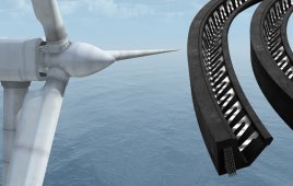
For the highest possible capacity factor, wind farms are sited where they will be exposed to as much consistent wind as possible. Consequently, all parts of a wind turbine are subjected to extremes of weather, ozone, unusual stresses, and vibration. Things get worse offshore where they must also withstand the rigors of the sea including exposure to saltwater from continuous spray.
In addition to metal components in a turbine’s structure, there are many polymer-based components. These must be engineered to withstand the challenging operating parameters.
Unfortunately, well engineered seals are often overlooked in wind turbine components (see the editorial in this issue). A properly engineered sealing system adds to the mean time between component failures, reducing manufacturing costs associated with the use of exotic coatings, and trimming on-board power consumption due to unnecessarily high friction.
An advantage comes with knowledgeable material development. For example, not all PTFE seals perform equally, and not all fluoroelastomers are the same. Each specially formulated material recipe ensures control over its wear rate, coefficient of friction, extrusion resistance, damping factor, and fatigue resistance. Test facilities can then ensure the right combination of–among other things–wear factors, friction, and tan delta (for damping behavior) to provide the right material for each application.
Polymer seals are often used in the main and yaw brakes, main gear, main bearing, lock cylinder, pitch cylinder, and a turbine’s hydraulic accumulator.
Each component is integral to the performance of the wind turbine. Take, for example, the seals in a hydraulic actuator. In continuous-pitch systems where the angle of the blades changes on average 15 times/min, the actuator initiates close to 8,000,000 strokes annually. One such unit sports a seal mounted to a module that quickly bolts on and off.
In addition to high cycles, seals must operate at over 3,000 psi with constant pressure on the rod from behind and differential side loads that control positioning. Standard applications require a temperature resistance to -22°F with -40°F required in the Arctic, and a maximum standard capability of 140°F. The lost revenue from reduced efficiency and the high cost to replace prematurely failed seals punctuates the need for proper seal choices. Hence, a lot of R&D goes into developing the right seal materials, as well as in testing their performance in high pressure, wide temperature ranges, and with heavy side loads.
Offshore turbines use one of the largest and unusual seals. Turbines there mount on monopiles and tripods, designs that depend on soil properties and water depth. For monopoles, the pile is driven into the sea bed so its top is about 16 ft under water. A transition piece, about 82-ft high, is lowered over the top of the pile. The space between the pile and the transition piece is sealed by an inflatable grout seal about 16-ft. dia., the largest on a wind turbine. This seal closes a substantial gap and simultaneously resists an internal pressure of a few psi. Grouting (a cement) the space above the seal results in a strong joint. Lastly, a floating crane installs the tower and the turbine.
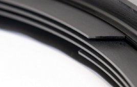
A manufacturer of hydraulic actuators specified an unusual configuration that would enhance lubrication and friction characteristics while preventing leaks. The solution is a complex arrangement of seals ranging from O-rings to specialized and proprietary Turcon PTFE-based geometries and Orkot composite materials. The latter material is an advanced non-metallic reinforced polymer composite. A third component is made of a bearing material that prevents metallic contact between the sliding parts of a cylinder. WPE
Filed Under: Seals & slip rings