 Although many wind farms in the U.S. are generating electricity and well beyond a testing stage, their debugging continues. Many of these turbines suffer design-related failures within their first few years of operation.
Damaged bearings, for instance, can cause generator failures, which lead to unplanned downtime and costly repairs. If down for a month, a failed 1.5-MW generator can account for over $48,000 of lost revenue, and a single month’s wait for parts is unrealistically short considering the worldwide shortage of bearings and other key components. On top of lost revenue, the cost of repairing failed bearings (newbearings, labor, slip rings, and other parts) can run as high as $50,000. This figure still does not include the enormous expense of renting and transporting the large crane needed for many repairs. And there is often a long wait for that as well.
Though often hidden by manufacturers’ warranties, the full cost of the failures can be quite high. Case in point: A wind farm in Oregon was plagued by repeated bearing failures. In addition to high repair costs, the owners were losing revenue due to unacceptable periods of downtime. They were also baffled by the cause of the failures.
The local representative for a manufacturer of bearing protection rings called on the wind farm and obtained permission for up-tower testing. Results revealed the bearings were being “fried” by generator shaft currents much like those seen on ac motors controlled by PWM inverters (variable frequency drives) in industrial HVAC, pumping, and processing equipment. The problem appears worse in the doubly-fed-induction generators. In this design, the stator is directly connected to the mains, while the rotor is fed by a voltage-source inverter.
When reliability engineers pointed out similarities and identified shaft currents as the suspected problem, they were allowed to install a conductive-microfiber bearing protection ring intended to protect wind turbine rotor bearings. Results indicate that this ring appears to have solved the chronic bearing failure problem.
A sequence of failures
Problems at the wind farm unfolded this way: The generator bearings in one wind turbine failed only 11 months after the unit was brought on line in May 2006. The windfarm operator replaced the bearings and slip rings, only to see the new bearings fail five months later. Again, new bearings and slip rings were installed.
A third bearing failure came 11 months later. This time, in addition to replacing a set of insulated (ceramic-coated) bearings and slip rings on both ends of the generator, the owner decided to try a conductive microfiber bearing-protection ring and shaft collar with a high conductive surface on the drive end. All components come from AEGIS and were installed by the regional distributor on September 12. Also replaced were two standard carbon-block brushes which rub on the slip ring at the non-drive end.
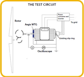
Three months later the crew used a probe and oscilloscope to measure shaft voltage on the generator with and without the new bearing-protection ring and collar engaged. All measurements were taken on the same circuit. Wind speed ranged from 10.2 to 13.4 mph. Data from the field tests show the conductive-microfiber bearing protection ring and collar reduced shaft voltage by an average of 84.5%.
The first measurement, taken during full-power operation with a wind speed of 12.1 mph, established a baseline voltage (the system’s ground noise level) of 2.60 volts (peak-to-peak) from the 5.824-in. dia. shaft of the turbine’s doubly fed, asynchronous 1.5- MW generator.
The crew conducted eight more measurements in two series. The Series 1 readings measured the shaft voltage with all components engaged. The bearing protection ring and collar were on the drive end of the shaft, and the standard carbon block brushes were on the non-drive end. For the Series 2 readings, the bearing protection ring was disengaged and the shaft collar removed, leaving the carbon block brushes on the non-drive-end as the only shaft-current mitigation path.
A closer look
High-frequency currents induced on the shaft of a doubly-fed induction generator come from parasitic capacitive coupling and can reach 60A and 1,200V or more. If not diverted, these stray currents discharge to ground through the generator’s bearings, causing pitting and fluting (just as electrical discharge machining would) that result in premature bearing failure and catastrophic turbine failure.

Bearing damage has become the Achilles’ heel of this widely used generator. In it, stator windings are directly connected to the main power grid, while slip rings connect the rotor to a voltage-source inverter which uses a small fraction of the total windturbine power.
The rotor-side converter regulates the electromagnetic torque and supplies part of the reactive power to maintain constant voltage and frequency of the stator output and the power grid. This design makes it possible to use varying wind speeds while maintaining a constant stator voltage and a constant frequency output to the grid. Because the inverter’s rating can be as low as 25% of the total system power, the design also reduces inverter cost. However, the system’s high-frequency switching introduces the dangerous rotor-shaft voltages, exposing bearings, gear boxes, and other critical generator components to high-frequency currents.
Even large motors show that inadequate generator-shaft grounding significantly increases the possibility of electrical bearing damage. Viewed under a scanning electron microscope, a new bearing race wall has a relatively smooth surface. As the shaft turns, tracks eventually form where ball bearings contact the race wall. With no electrical discharge, the race wall is marked by nothing but this mechanical wear. Without proper grounding, electrical discharges begin at startup and grow progressively worse, scarring the race wall with small fusion craters. In a phenomenon called fluting, the operational frequency causes concentrated pitting at regular intervals, that form washboard-like ridges.
Mitigating bearing damage
To guard against electrical damage to bearings, stray currents must be diverted from the bearings by mitigation devices such as insulation, special current filters, an alternate path to ground, or some combination of these. The devices vary in terms of cost and effectiveness.
Insulating bearings is a partial solutionthat more often than not shifts the problem elsewhere. Blocked by insulation (usually an exterior coating of aluminum oxide), stray currents seek other paths to ground. Attached equipment, such as gearboxes, often provide the path, and frequently wind up with bearing damage of their own. In addition to being expensive, insulation is subject to contamination. Worse yet, some types of insulation can be totally selfdefeating. In certain circumstances, the insulating layer has a capacitive effect on high-frequency induced current, letting it pass through to the bearings.
Nonconductive ceramic bearings, often called hybrid bearings because the balls are ceramic but the rest of the unit (including the race wall) is metal, can divert damaging currents but leave attached equipment open to damage of its own. Due to high voltage potentials across their surfaces, the ceramic balls can also be pitted and eroded by electric discharge similar to “static electricity discharge”.
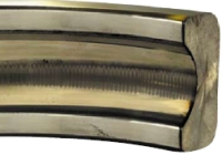
Damage to a generator’s bearing race occurs for the same reason EDMs work: An electric current through the balls chisels away at the race metal.
Another mitigation tactic uses conductive grease, in theory, to bleed off harmful currents by providing a lower-impedance path through the bearings. In practice,however, the conductive particles in the grease increase mechanical wear.
Special dv/dt current filters or common mode current filters can mitigate damaging currents in some circumstances, but field results have been mixed at best. More effective is a sinusoidal filter which allows a nearly sinusoidal line-to-line voltage at the motor terminal. However, the filter does not suppress the common mode voltage, so this option reduces the generator’s efficiency due to motor losses and noise.
Conventional spring-loaded carbon block brushes certainly help. They contact the motor shaft to provide an alternate path to ground. Unfortunately, they too have drawbacks. They are notorious for the maintenance they require, due primarily to wear. Tiny particles break off from each brush. They also build up on the generator shaft, sometimes diminishing the brush’s effectiveness only weeks after installation. Carbon block brushes also require a narrow humidity band. Levels too low or too high are detrimental to their performance.
A solution
Alternate discharge paths to ground, when properly implemented, are preferable to insulation because discharge paths neutralize shaft current. An ideal solution would provide an effective, low-cost, low resistance path from shaft to frame, affording the greatest degree of bearing protection and maximum return on investment. The AEGIS WTG Bearing Protection Ring from AEGIS SGR (www.est-aegis.com) meets the criteria. It uses principles of ionization to boost the electron-transfer rate and promote the efficient discharge of the high frequency shaft currents induced by many wind turbine generators. It safely channels harmful currents away from the bearings to ground.
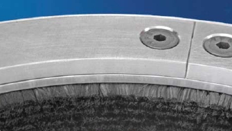
The ring surrounds the generator shaft with millions of conductive microfibers, each less than 10 microns diameter. The fibers, stiff and strong yet flexible, provide high-density contact points — parallel paths of least resistance from the motor shaft to ground. The fibers significantly reduce voltage buildup on the generator shaft by conducting instantaneous currents of many tens of amperes and discharging from tens to thousands of volts with MHz frequencies. The ring is especially suitable for use at high frequencies because its fibers tend to compensate for variations in the roughness of the shaft surface, or microscopic misalignment of the ring and shaft, or both. When a microfiber looses mechanical contact with the rotating shaft, electric contact is quickly re-established somewhere else along the ring, due to local field emissions.
A phenomenon called gaseous or electric “breakdown” can generate a gap (greater than 5 microns) between shaft and fibers. It is a cascading effect of secondary electrons that comes from collisions and the impactionization of gas ions accelerating across the gap. With a smaller gap (5 nm to 5 μm), field emissions generate a phenomena called Fowler- Nordheim tunneling in which electrons “tunnel” through a barrier in the presence of an electric field.
Thus, the ring fulfills all functions of conventional spring-loaded carbon brushes with neither the hot-spotting, thermal wear, nor the direct frictional wear common to such brushes. Because its multiple microfibers dissipate heat better than singleconductor devices, the ring tolerates higher current densities. Furthermore, unlike carbon block brushes, microfibers on the bearing protection ring are not adversely affected by oil, grease, dust, moisture, or other contaminants.
In addition, the bearing protection ring safely diverts shaft current at frequencies up to 13.5 MHz and discharges up to 3,000 volts (peak). The ring is maintenance-free for at least two years, effective at any shaft speed, and available for any size generator. The ring www.windpowerengineering.com DECEMBER 2009 Windpower Engineering 4 9 is also suitable for up-tower retrofits and preventive-maintenance programs as well as for OEM installation. A split-ring model makes on-site retrofits faster and easier than previously possible. And coating the shaft collar with conductive silver paint enhances the ring’s effectiveness.
Results from a series of tests of a turbine with the bearing protection ring installed show an average generator shaft voltage of 6.41 V (peak-to-peak). Results from a second series of tests using only the spring-loaded carbon block brushes show an average shaft voltage of 41.35 V (peak-to-peak). The difference between these averages, 34.94 V, indicates that the bearing protection ring and collar successfully divert about 84.5% of the damaging current that remains on the turbine’s generator shaft when carbon block brushes at the non-drive end are the only form of bearing protection. Furthermore, the voltage wave form with the AEGIS ring and collar engaged was a smooth wave without detectable discharge to the bearings, while the wave form without the ring and collar showed a bearing-current-discharge pattern with voltage peaks an average of 6.5 times higher.
Similar tests at a facility in Texas on a 1.5 MW wind turbine generator manufactured by another supplier yielded similar results. The ring reduced a shaft voltage from over 600 (continuous) to 30 to 40V (peak-topeak), safely diverting 50 to 60A.
AEGIS SGR
Filed Under: Bearings, Generators, Safety


It is very important to find a way to protect bearings,thrust bearing varieties can enable rotation, support and drag and are vital for automotive, marine, and aerospace applications. Ball screw bearings help promote precision in machining, aircraft, robot, and semiconductor production. Needle bearing models employ small rollers to help reduce friction of rotating surfaces.Slip ring also can be used in wind turbine.
More information http://www.arslipring.com
The type of slip ring has relatively high maintenance cost, and the dust produced by friction is easy to accumulate,
more information:http://www.moflon.com