Jesse Tarr
Jesse Tarr / President / Windsecure
Anchor bolts secure a variety of structures to foundations. Wind turbines are just one such structure. Loose anchor bolts will allow excessive fatigue the foundation’s reinforcing steel, grout, and concrete. This fatigue eventually leads to larger, more expensive problems such a grout and concrete failures, all of which jeopardize the foundations functional longevity.
Consider a circle of anchor bolts, such as those that hold a turbine tower to its foundation. A deviation in tension from one bolt transfers uneven loading to surrounding bolts, leading to non-uniform pressure on the structure’s foundation. As more bolts loosen the problem propagates and when left unchecked, can lead to a catastrophic structural failure.
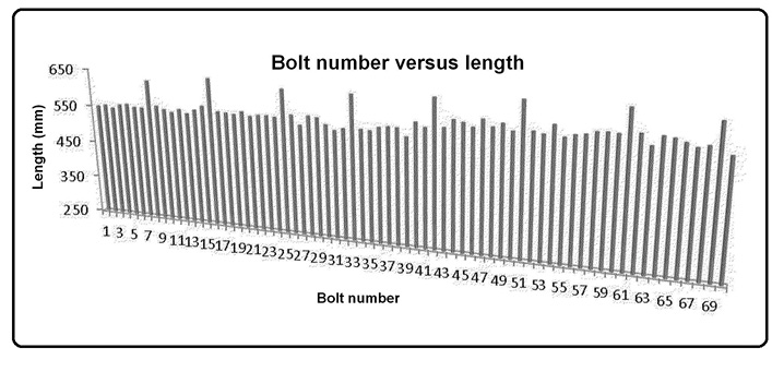
The graph plots anchor-bolt stretch in millimeters as a function of bolt number around a structure.
Anchor bolts come loose for many reasons. A few include failure of the supporting grout, improperly tensioned anchor bolts, and failure of the supporting foundation, such as fracturing or uneven settling. It is important to establish precise records of bolt tension to better determine if there are issues, and the possible root cause of changes in bolt tension.
With regard to a wind turbine, a base section out of level by fractions of an inch will lead to several inches or feet out-of-level at the top of the tower. The generator, gearbox, and other components at the tower’s top must be precisely balanced for the wind turbine to operate properly. When such components are out of balance, it leads to the failure to one or more of them and the costs to fix such issues are extradinary.
We have devised a process for improving a structure’s integrity that includes measuring anchor bolt stretch, correlating that to an exact “as found” tension, and re-tensioning several anchor bolts on the structure to a final load P. In a nutshell, bolt stretch, B is measured for each bolt in a set. The integrity of the structure is found by solving the equation for each anchor bolt:
F=kP−(BAE)/L
where F = the calculated load on a bolt; P = a bolt load found from test; B = a measured bolt stretch from the load F to final load P;
A = the cross sectional area of the bolt;
E = bolt material’s modulus of elasticity,
L = a length of bolt under tension, and k is a unit specific constant.
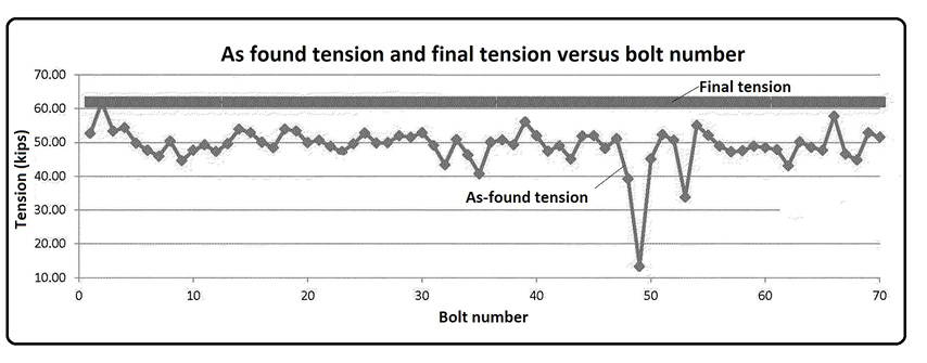
The plot is for as-found (F value in the equation and denoted by diamonds) and after tensioning (P value in the equation and denoted by squares) for the bolts of the previous illustration.
By monitoring a set of anchor bolts after about a year for changes in F, and at least for one bolt, anchor-bolts changes in the structure can be detected and repaired before further damage occurs. A failing structure is assessed in several ways including evaluating the F values as a function of the bolt position in the bolt circle.
The corrective process requires a tension gauge and micrometer that measures an applied tension and bolt length, and a way to correlate these to the equation. This allows quickly determining bolt tension, adjusting it to a required value, and then identifying potential sources of the tension change.
The method here puts a known tension on an anchor bolt and measures a bolt’s axial length change. It is a simple way to find bolt tension prior to the test. Its tension is determined by solving the equation.
Because the equation is linear, it applies to a recommended load range and for a given bolt. However, it does not apply when a bolt is overloaded, beyond a maximum loading because its elasticity is lost and the bolt suffers irreversible deformation.
Consider this example to apply the equation. Let: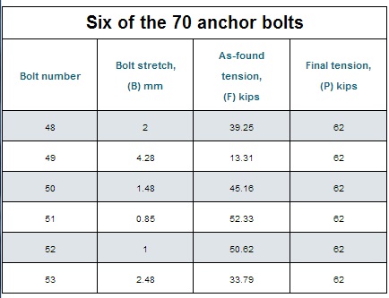
P = 62,000 lb or 62 kips
B = 0.0433 in.
A = 1.25 in.2
E = 29,000,000 (#10 grade 75) and
L = 124 in.
k = 1
Therefore:
F = 62,000 − [0.0433×1.25×29,000,000]/124
F = 49,342 lb, or 49.34 kips,
the actual load on the bolt.
Knowing A, E, and L, and by measuring values for P and B as part of servicing a structure, the equation provides F, the as-found bolt tension prior to retensioning to a required value P. The accompanying illustrations show the variation in values generated by solving the equation to map bolt length and tensioning profiles for the structure. The structure is then evaluated based on these values for potential integrity problems.
Problems readily identified by this method include non-uniform foundation settling, defective anchor bolts, and anchoring system failures. There are others, and all can be investigated by conventional means and corrected before further damage.
To further illustrate, the following example came from a working turbine secured to its foundation by 70 anchor bolts. The anchor bolts are tested by the method described with the values of bolt elongation, as found, and final tension for each of the bolts being measured and recorded. Final tension is determined by a calibrating device of our invention.
In the example, bolts of particular interest are numbers 48 to 53 because they are under-tensioned. An investigation determined the area of loose anchor bolts had failing grout, which required repaire. Upon completion of an approved process for repairing the grout, the bolts are tested again and found to be holding their required load, thus ensuring operational reliability of that structures foundation anchoring system. 
Filed Under: News, O&M