If new techniques do not bring down costs of constructing wind farms offshore, the industry will be difficult to justify outside of government largess. Fortunately, the two ideas here suggest that is quite possible to take sharp knifes to high costs.
Paul Dvorak / Editor
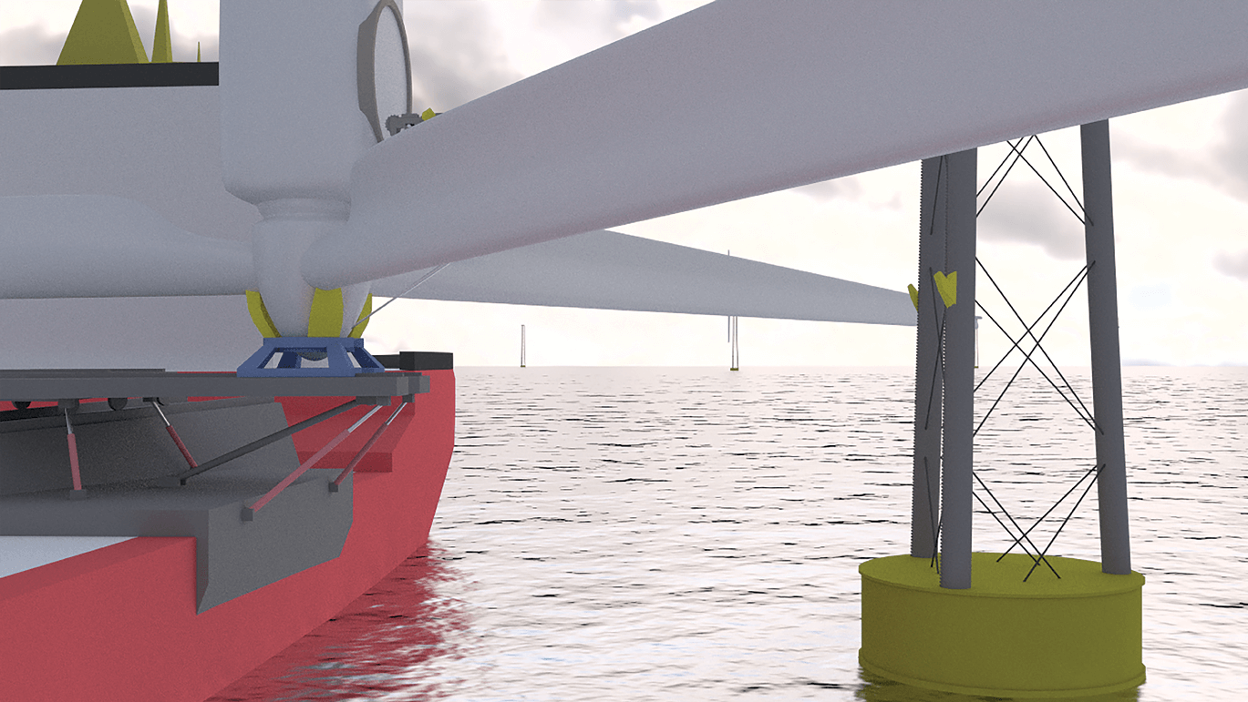
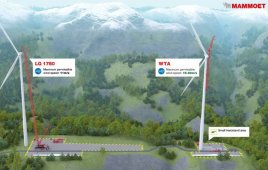
A transport barge with a rotor and nacelle assembly approaches a tower. (Pick on any picture for a larger version.)
Building offshore wind farms is outrageously expensive, especially for the nascent U.S. wind industry which is on a steep learning curve. The only wind farm in U.S. waters is reported to have cost around $300 million for five turbines with a modest combined capacity of 30 MW. Obviously, costs will have to come down if the industry is to grow. Even though the European developers have been working in offshore wind longer, they have also struggled with costs.
Good news: There is no shortage of ideas for cutting costs. Of the ideas presented here, one proposed design lets a carriage climb a prepared tower to place the nacelle and rotor without a jack-up vessel. In the second, a specially designed ocean-going barge serves as
The barge and a carrier transfers the nacelle and rotor off to a mechanism on the tower.
production platform and delivery vessel for a large spar buoy and wind turbine. This idea works best for the deep water around much of the U.S. that prohibits seabed based foundations prevalent in European waters. Here’s a closer look.
Goodbye jack-up vessels, hello SENSE
A new wind-turbine installation and maintenance idea could cut the cost of energy from future deepwater sites by around 9%, and from nearshore sites by 4%. That is the conclusion of a £200,000 ($260,000) detailed analysis by the Innovate UK Energy Catalyst on the Self Erecting Nacelle System (SENSE, senseoffshore.co.uk ). The study suggests that the technology could let industry dispense with the costly use of jack-up vessels.
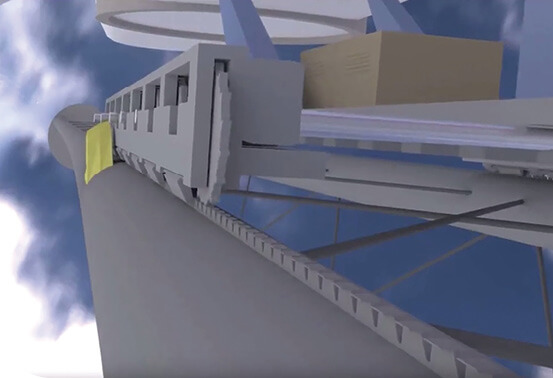
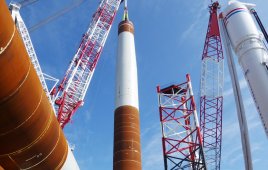
The carriage ascends a tower with the nacelle and rotor (top, off the photo). The SENSE team has also designed a tower to accommodate the system.
SENSE calls its invention a modular, removable transport, and installation system that mounts on a standard large construction vessel. It would also serve maintenance tasks including the change out of larger turbine components.
The company says there is currently no proven technology capable of installing the next generation of turbines and towers on foundations in water depths greater than 60m, apart from building larger and more expensive jack up vessels.
“Wind turbines are getting bigger and developers want to exploit deep-water sites,” said Sense Offshore Managing Director Patrick Geraets in a press release. “How are these turbines going to be installed? SENSE is an answer – faster, cheaper, independent of water depth, with worldwide application, and it is scalable to the larger turbines coming to market in the next five years.”
It works like this
In a nutshell, the system consists of a multi-purpose construction vessel capable of carrying two or three turbines, a mechanism for transferring the turbine to the tower, and a tower-climbing device. The company says this arrangement is capable of transferring loads of up to 700 tons from vessel to tower, and in significant wave heights. Geraets says the high weight capacity is intended to handle the coming 10+ MW turbines.
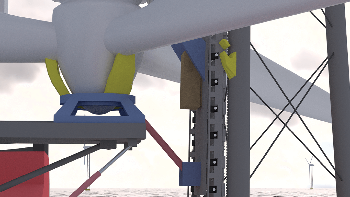
At the tower top, a hydraulic system on the carriage rotates the nacelle 90° and places it on a tower platform. The construction crew then bolts the nacelle in place.
The nacelle and rotor are assembled at the dockside with the rotor flat on the deck with the nacelle vertical. The transport carriage is fitted to the rotor assembly.
The construction vessel transports the rotor assemblies to the wind farm where towers have been installed in a conventional manner. Each rotor-nacelle assembly rides on permanent rails onto a handling system on the vessel, which uses heave-compensated positional control (compensates for ship movement) to target and coordinate a transfer to rails mounted on the tower. Once the rotor assembly locks onto the tower, the vessel detaches and moves away to install another turbine.
A crew in the tower connects a power and control umbilical to electric power so the rotor assembly can climb the tower on the transport carriage. The carriage clamps to and climbs ratchet rails on the tower, like a cog railway. The rotor assembly is supported at its center of gravity with the blades fixed horizontally until it reaches the top of the tower.
There, hydraulic equipment pivots the rotor assembly 90° and the transport carriage lowers the rotor assembly onto the tower. A crew bolts it into place. Once secured, the transport carriage returns to the bottom of the tower where it is retrieved by the construction vessel. In rough weather, the rotor nacelle assembly might remain at the base of the tower until the weather improves.
Geraets says the tower tracks will be permanent. “We estimate they add about 10% to the cost of a standard tubular tower. However, our proposed three−legged lattice tower, which will match the use of SENSE lowers the cost of the tower with tracks by a conservative 8% below a tubular tower and equivalent to 0.15% off the LCoE. This design will be suitable for monopole, jacket fixed foundations, and all types that float”
Conventional installation methods average around 24 hours per turbine, but Geraets’ team suggests that turbines can be installed in parallel using several SENSE-equipped vessels for a shorter construction program. Shorter installation periods significantly reduce the construction-finance risk profile, and the interest costs of large wind farms by generating early revenue. What’s more, weather-critical operations span a shorter duration, letting the system take advantage of narrow weather windows. The company also says the concept easily scales to projected 10 MW+ turbines, while the market may not quickly provide large crane vessels to keep pace with this development curve.
The study
The Innovate UK study was carried out for SENSE Offshore by a project team of contractors including GBG, PHG Consulting, Industrial Systems and Control, BVG Associates, Knowtra and James Fisher Marine Services. In deep water, 70m and more, the study estimated the system could slash around $147 million from the capital expenditure (CapEx) on a $6.6 billion, 1,200-MW wind farm and trim $33.5 million each year off operating expenditures (OpEx).
In shallower sites with water depths similar to the North Sea, where farms are served by jack-up vessels, the study says the technology could save $99 million in CapEx and $11.7 million in OpEx per year. CapEx savings come in part from the use of more readily available construction vessels at competitive prices. These vessels can be mobilized at shorter notice than crane vessels.
OpEx gets significant cuts because large crane vessels are not needed for major component replacements, leading to lower mid-life refurbishment costs. In the event of a major failure, the complete nacelle and rotor assembly can be “swapped out” without replacing the individual components. The result is a turbine that is back up and working in one weather window.
In addition, the study says SENSE would improve access for external O&M turbine inspections. In particular, it can provide a mount for a secure platform for blade inspections and repair.
“A partner or investor could be an existing construction company looking to expand its offering to the offshore wind industry to include large turbine installation and maintenance, or a new entry eyeing this growing and substantial market,” said Geraets.
A patent covering the SENSE installation system has been filed and the company is planning the next stage of its development, a working prototype, which would bring the technology to market by about 2020. A good animation of the system is here: tinyurl.com/SENSE-animation.
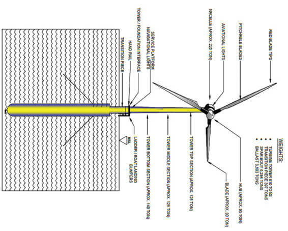
The drawing provides a few details for a completed buoy and turbine.
Construction and delivery on one vessel
The first floating wind farm, launched this year off the coast of Scotland, uses several huge spar buoys made of steel rolled and welded by conventional methods. While many developers are convinced the spar buoy is the ideal floating platform, a few suggest there are better ways and materials to manufacturing the buoy.
“The consensus of developers working with the designers and universities is that the spar buoy design offers one of the best solutions as a floating substructure for turbine foundations,” says AMFConcepts Principal Andrew Filak.
He says the structure, characterized by a small water-plane area and a large cylindrical mass below the surface, has found increased favor in deep-water applications. “Spar buoys have been designed for installations in depths of 400 to 2,400 feet. The buoys’ draft of 360 feet below the surface helps resist the heave motion. Ballast placed low in the buoy gives the system a low center of gravity making it quite stable and resistant to pitching and rolling assisted by its station-keeping design,” he says.
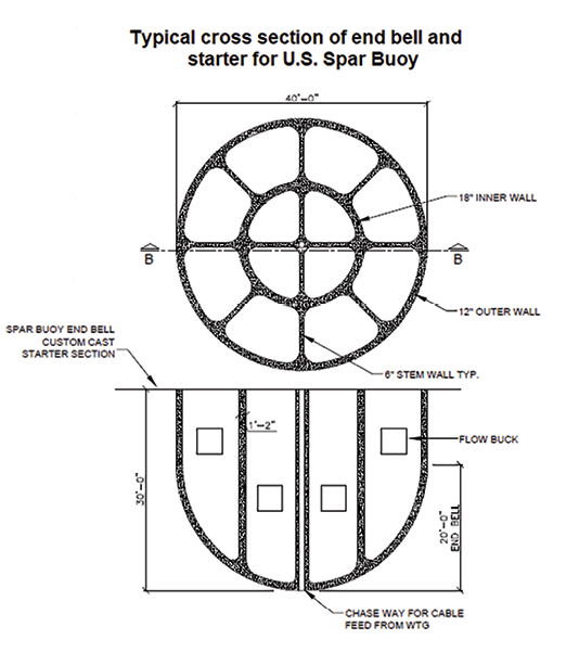
Buoy construction is executed dockside. The first component, an end-bell starter section, measures 40-ft diameter by 30-ft high. This first component is cast on the dock and then set into a lowering well on the barge. The slip formwork and its staging are placed in four pie-shaped quadrants onto the end-bell starter.
The problem, as with most work offshore, is the cost. Filak says the turnkey cost in 2017 for a 7-MW floating deployment using conventional materials and methods is $50 million.
The turbines carried by the buoys would be direct-drive designs because they offer developers of deep-water offshore sites the potential to capture the market with significant cost savings. The costs would be done by delivering a fully assembled 7-MW direct-drive design to a deep-water site at a turnkey cost in 2018 for $35 million.
The turbine, station keeping equipment (anchors and cables), power-feed costs are the same. The significant differences are in the construction of the spar buoy, assembly, and commissioning of the turbine. The costs cited include transport of both components to the site, tie down, and placement of the turbine atop the buoy.
Filak calls his design the U.S. Spar Buoy (USSB) foundation and recommends building it using a geopolymer concrete. Geopolymer is a material that, unlike steel, does not degrade in seawater. The Zeobond Group in Australia is one manufacturer of the material. Reinforcement would come from a corrosion-resistant, steel-free rebar.
Construction begins and ends on an ocean-going deck barge built to construct the spar buoys and deploy them to a deep-water wind farm.
The illustration provides a closer look at a few spar buoy details.
How it’s made
The buoy is made by slip-forming the concrete, a method similar to extruding a material. This method addresses the major problem of forming a large, round tube-type structure with internal struts tied to a second internal tube. The design makes it easier to place rebar and concrete. The concrete mix would slip form at two feet per hour, which requires a formwork heated to 85°F minimum to heat cure the material.
This form rate is a big plus because it provides fully cured concrete in 24 hours. “This feature lets the slip form rise at four times normal placement, and achieves a port-to-site production window of under two weeks for the construction and deployment of the turbine,” he says.
The greatest threat to marine concrete structures is water, either fresh or salt. “With time, water penetrates conventional concrete through unseen cracks and natural porosity and rusts steel rebar. Even protective rebar has coating failures and deterioration. Seawater also directly attacks the chemistry of conventional (Portland) cement causing rapid failure. What causes a conventional binder to fail at sea is a high percentage of Calcium compounds, about 70%, which come under attack by the Sulphur compounds in seawater. This rots the concrete. Polymer concrete, however, has an expected life of nearly 100 years and would let a spar buoy support at least three generations of wind turbines,” explains Filak.
The barge
To avoid the expense of conventional manufacturing methods, Filak’s company has designed a buoy-building deck barge. “It will comply with the 1920 Jones Act, which allows only qualified U.S. vessels built domestically and crewed by U. S. citizens to carry cargo from U.S. port to U.S. port,” he says.
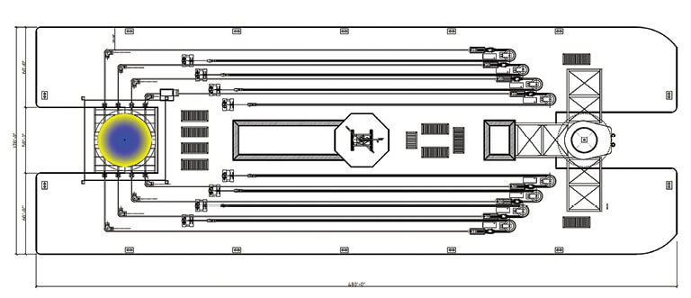
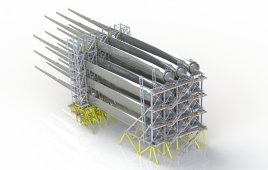
The deck plan (a top view) shows on the left, winch cables and the spar buoy work area, and on the right, where the transition piece and wind turbine would be assembled. The dual-hull catamaran barge measures 480-ft by 60-ft wide connected by a bridging structure 300-ft by 50-ft by 10-ft deep flush with the deck plate and centered fore and aft on the outside hulls. This provides a deck plan of 72,600 ft2.
The barge serves as a construction, transportation, and deployment platform all in one. The barge is secured dockside with ready access to materials and resources while the spar is slip formed at one end. At the same time, the wind turbine is assembled at the other end. When construction of the buoy finishes, its own
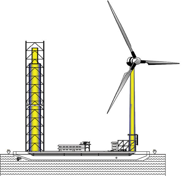
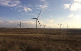
A completed spar buoy and wind turbine would look like this leaving the assembly quay for the deployment area.
propulsion will move it out to the wind-farm site with both components onboard. Onsite, the spar is deployed at 50 foot-per-hour into the water, water ballasted down, and moored into location by standard station-keeping methods. The barge then rotates 180° to mount the wind turbine’s transition unit over the spar, which is then de-ballasted, joined, and mechanically locked to the transition component to support the turbine.
Two developments make it possible to build on the barge. One is a multi-functional structural tower, on the left in the barge drawings. It is made of high-strength, man-lift mast sections. The port side, forward leg of the tower supports a rack-and-pinion man lift. The second development is a water ballast system that keeps the barge balanced as the buoy is slip formed upward. At the other end of the catamaran barge, the transition component supports the turbine as it is assembled over the forward slot.
Filak says this opinion, with accurate input, identifies a unit cost at $5.2 million per spar buoy (excluding the cost of the turbine) for construction, assembly, and delivery, in under two weeks, to a station-keeping crew in a 100-unit wind farm. This installation cost is a fraction of the current floating-foundation costs.
Another plus: The geopolymer concrete cement binder supports aggressive global carbon reductions by producing 80% less CO2, and in a much shorter fabrication process. Readers can find more detail of AMFConcept’s barge and buoy here: tinyurl.com/buoy-barge. 
Filed Under: Construction, Offshore wind