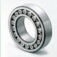
Turbines use a wide variety of bearings. Large ones include huge 2-m diameter main-shaft bearings with two opposing rows of cylindrical rollers to handle enormous thrust and radial loads. These support the shaft that holds the hub and rotor. Slew bearings mount between nacelles and towers to let nacelles rotate as needed. These can have 3 to 6-m diameters with gear teeth machined into outer ring surfaces.
Another bearing, a hybrid design, aimed at wind-turbine generators provides insulation against electric currents. Their use can minimize the risk of premature bearing failures due to erosion from electric currents. The manufacturer says the units can maximize lubricant effectiveness for long-term performance, even under poor lubrication conditions.
These ball bearings are said to benefit from a deep groove that combines steel rings and bearing-grade silicon nitride (ceramic) rolling elements. The balls are lighter, harder, less dense, and more durable than all-steel bearing counterparts, and they conform to standard bearing dimensions.
Benefits to its use are said to include higher reliability than conventional bearings along with reductions in life-cycle costs, total operating costs, and maintenance requirements. The bearings can supposedly upgrade existing wind-turbine generators without redesigning them.
Custom bearing may be a solution where conventional designs have come up short. Products of several bearing manufacturers support pitch, yaw, and gearbox applications in systems from 200 kW to 5.0 MW. The firms can design bearings to meet performance and life requirements with the most economical bearing design. Experience with offshore applications help specify appropriate corrosion resistant coatings such as zinc, paint, or other surface treatments. Material requirements can be met for operating temperatures down to –40C and below.
Other bearings appear conventional but have been modified. For example, in an electric environment, electrolytic corrosion from stray currents threatens bearing performance. One design uses coated angular-contact ball and cylindrical rollers to insulate the bearings from electric current. A ceramic coating applied to the outer surface and side faces of the outer ring prevents current from passing though the bearing. The design provides an insulation resistance of at least 2,000 MΩ. Under normal operating temperatures, this alleviates electrical arcing and early failure. The bearings come with or without seals or shields, and are interchangeable with standard, non-insulated bearings. The units are usually available with bores of 50 to 160-mm dia.
Another way to handle stray currents provides a discharge path to ground. One solution would provide a low resistance path from shaft to frame. A device called a bearing-protection ring meets the criteria. It uses principles of ionization to boost its electron-transfer rate and promote the efficient discharge of the high-frequency-shaft currents induced by many wind turbine generators. It channels harmful currents away from the bearings to ground.
The ring surrounds the generator shaft with many of conductive microfibers. The stiff yet flexible fibers provide high-density contact points — parallel paths of least resistance from the motor shaft to ground. The fibers reduce voltage buildup on the generator shaft by conducting instantaneous currents of many tens of amperes and discharging from tens to thousands of volts with MHz frequencies. The ring is especially suitable for use at high frequencies because its fibers tend to compensate for variations in roughness of the shaft surface, or microscopic misalignment of the ring and shaft, or both. When a microfiber looses mechanical contact with the rotating shaft, electric contact is quickly re-established somewhere else along the ring, due to local field emissions.
Filed Under: Bearings, Nacelle


