 Slowing and halting an 80-m-turbine rotor involves converting its kinetic energy into heat. Of course, there are several design decisions here. Rotor brakes control overspeed, and provide parking and emergency braking. These brakes can mount on the rotor or low-speed shaft, on the generator (high-speed shaft), and both shafts in some cases.
Low-speed-shaft braking is relatively straightforward in that a large disc brake, with a large friction lining area, is easy to accommodate. The drawback is that the brake must generate a high-braking torque.
Generally, the most cost-effective position is on the high-speed shaft between a gearbox and generator. The increase ratios of wind-turbine gearboxes produce a large reduction in output torque. In many cases, a major parameter regarding brake selection is choosing a friction-liner area of sufficient size to ensure adequate heat dissipation during emergency stops.
The energy to dissipate is the same regardless of brake location, so the total lining area must be the same. The brake-pad area must be sufficient to control the temperature rise.
These requirements are more difficult to meet on the high-speed shaft because speed and space are limiting factors with regard to the maximum disc diameter and brake selections. Nevertheless, braking on the high-speed shaft has been used on many turbines up to 750 kW. As the industry develops higher capacity turbines, the trend is leaning towards rotor-shaft braking.
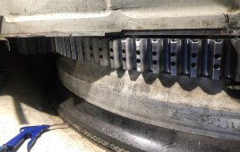
A further consideration regarding brake position is the possibility of gear tooth damage. If brakes are installed on the gearbox-output shaft and the turbine is stationary, gusts are likely to cause the rotor to transmit a rocking motion within the backlash of the input and output gears. Without forced lubrication between the mating teeth, this effect could ultimately result in fretting and expensive gear damage
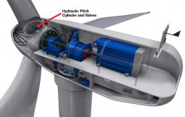
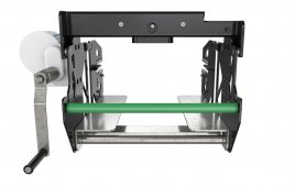
Pitch drive brakes: A series of high-torque, electrically released, spring engaged, static holding brakes can withstand the conditions on the pitch drive of large turbines. This brake is typically smaller in diameter than the motor assembly and adds minimal length to the overall package. One model, rated at 135 Nm, is 6.5-in. diameter and only slightly over 2-in. long. Typical design life calls for 500 to 1,000 stops. Some brakes exceed this range. Another plus for electric brakes: A short reaction time, 0.20 sec or less, making it a good choice for pitch drives.
A braking torque level for rotor brakes is one characteristic to calculate during initial stages of brake design. The maximum permissible braking torque on a rotor shaft is usually imposed by the blades, or their anchorage to the gearbox input shaft. On the other hand, braking on the high-speed shaft is usually related to the maximum permissible gear-tooth loading.
There is also a minimum level of braking torque, below which the variable nature of the frictional forces under different operating conditions could put a turbine rotor at risk.
It is therefore important to allow an adequate window of safety, or service factor, to ensure that the brakes will always operate effectively and under all climatic conditions. To achieve an adequate service factor it is helpful to consider how braking performance can vary with the same predetermined level of braking torque.
For example, suppose a turbine has a 1-MW rating, and aerodynamic (load) torque of 100,000 Nm.
Applying a brake during an emergency at 20% over-speed, the rise in disc temperature and stopping time will vary depending on the chosen service factors. A commonly applied factor of 2.00 suggests:
Tb/TL = 2
where Tb = brake torque and TL = load torque.
Hence, the calculated braking torque Tb = 200,000 Nm.
Filed Under: Pitch & yaw
Established in 2009, MOE Brakes is one of the top online Brake/Wheel
Hub distributors in Canada. Our site averages 1 million unique visitors every month.
Customers can get up to 75% off on regular retail prices.Shopping at MOE Brakes