Data and communication cables are essential to wind-turbine operations. To meet the physical demands and harsh-operating environments, fiber optic and Bus-Ethernet cables have advantages over others.
Uwe Schenk / Global Segment Manager – Wind • HELUKABEL USA • www.helukabel.com
Wind turbines are one of the most highly automated pieces of industrial equipment. By sensing changes in the wind, turbines simultaneously change blade pitch, or rotate to change direction to capture the best air currents. To perform these movements with precision, turbine components are connected with hundreds of feet of data and communication cables. When faced with the challenge of deciding what cable types to choose, engineers often focus on two – fiber optic and Bus-Ethernet.
A flexible fiber-optic cable is needed for wind-turbine applications to resist permanent bending and movements.
Fiber-optic cables
One benefit of fiber-optic cables is they solve data communications problems over long distances, making them an appealing option for many industries. To put “long distance” into wind-turbine perspective, the longest working fiber optic-transmission line is approximately 560 ft.
The cable’s signals also withstand magnetic fields that change with electric currents. Fiber-optic cables can transmit data almost noise free and at high bandwidths. A drawback, however, to fiber optic cables is that their small size makes them susceptible to damage or cutting during installation or construction activities. Standard fiber-optic cables used in infrastructure applications are extruded with a thin polyvinylchloride (PVC) jacket or with a heavy PVC jacket when used in ground applications. Unfortunately, neither option meets industrial demands and requirements.
The challenge for cable manufacturers is to create a fiber-optic version that can resist permanent bending and movements, such as torsion and mechanical stress in a wind turbine. Additionally, the cables must be sunlight resistant, when used in lattice towers. The cables must withstand low temperatures in turbines located in harsh-operating environments.
For wind-turbine applications, polyurethane or an equivalent insulation material is preferred for fiber-optic cables. Beyond the outer jacket and insulation materials, selecting a proper filler material, such as Kevlar for its re-enforcing strength, is important to ensure the cables can withstand the stress of turbine operations.
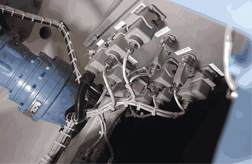
Fiber-optic cables connected in the rotor hub of a turbine (shown) keep the rotor speed within operating limits and monitors turbine operations.
Fiber-optic cables are ideal for data transfer and communication between wind-turbine components. This includes the pitch control system, which keeps the rotor speed within operating limits as the wind speed changes, and real-time data communication to monitor wind-turbine operations. Wind-tower compatible and pre-assembled, fiber-optic cables are two of their notable features.
Wind-tower compatibility: In an effort to be more efficient and improve performance, new generations of turbine towers are reaching unprecedented heights. Hybrid towers – concrete and steel – run up to 493 ft. high, while timber towers are capable of reaching heights of 460 ft.
Taller towers affect the transmission rate. Fiber-optic cables, such as polymeric optical fiber, and hard-clad silica (HCS) or plastic-clad silica (PCS) fiber optics reach their limits around 296 ft. and 427 ft., respectively. To address these concerns, controller companies changed the interface of the controllers to accept glass-fiber connections. The typical cable constructions are with 4/6/8/12 fibers G50/125 μm, G62.5/125 μm and E9/125 µm. The mechanical properties of the cables are now tailored to its construction, which factors in a higher tensile strength. The range of different types for tower applications depends on customer requirements. A minimum tensile load starts at 650 N with a transverse pressure of 40 N/cm, and increases up to 4,800 N with transverse pressure of 200 N/cm.
Other features of a fiber-optic cable include oil resistance, flame retardation, and most importantly, torsion performance. Cables should be tested and approved for a minimum of 5,000 cycles, and up to 18,000 torsion cycles. About 10,000 cycles complies with the expected lifetime of the wind turbine – about 20 years.
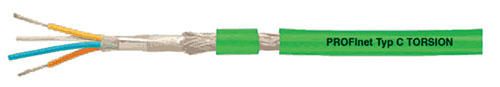
Torsion performance should be tested and approved for a minimum of 5,000 cycles, and up to 18,000 torsion cycles using a torsion-rated industrial Ethernet cable.
Pre-assembled, fiber-optic cable: Splicing cables and adding connectors onsite increases installation and maintenance times. An alternative is pre-assembled, fiber-optic cables which are tailored to meet the requirements of manufacturers and control system developers of wind-energy plants. The most widely-accepted design is a break-out adapter, which consists of a strong, two-piece housing fixed and filled with a fiber protecting material. It is available for 2/4/6/8/12 or 16/20/24 terminations of centrally-bundled conductor cables. The required connectors are stagger mounted for a simplified conductor break out.
Despite their small dimensions, pre-assembled cables are easy to install even under the most difficult conditions. The break-out conductors are protected by draw-in tubes that are easily removed from the adapter by a snap lock. The advantage of the snap-lock system is its ability to reproduce the assembly, including the protection tube, making it a preferred installation method. The permissible tensile load of this fiber-optic cable assembly is up to 550 N.
BUS-Ethernet communication systems
Copper cables using CAN Bus and Ethernet-PROFINET protocols are the ideal solution for wind-turbine communication systems located in close proximity to each other, such as between control systems in cabinets. One application, however, requires more attention. The electric pitch-control system, based in the hub, can only transfer power and data to the nacelle through the gearbox shaft. There is one problem with this application – the hub is rotating.
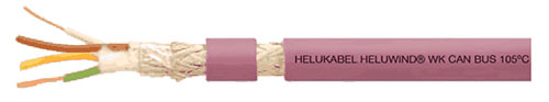
BUS cables are designed to withstand high temperatures.
A rotating slip ring solves the problem. It mounts directly on the hollow shaft of the gearbox, which permits the transfer of power and data cables to the pitch control system in the hub. The cables therefore are installed in the hollow shaft. The inner diameter of a hollow shaft ranges between 1.75 and 3 in., which is a tight space for five cables from 6 AWG up to 2 AWG plus CAN Bus cable 2x2x24 AWG plus Ethernet 2x2x22 AWG plus control cable 10×17 AWG.
There are several critical factors here to consider. One is the ambient temperature of the gearbox, which is about 158 to 176°F during regular operation, and a permanent vibration from the rotation of the rotor. Higher ambient temperatures in the shaft have a negative effect on a cable’s current carrying capacity. Also, the cables must resist an oil-like dust created by the turbine’s rotating components.
Such factors require a special cable mainly because a standard rubber or PVC-insulated cable cannot be used. The negative conditions speed the aging of installed cables, thereby reducing their overall useful life. The key requirements for cables in this application are 194°F conductor temperature, insulation material resistant to 221°F, small outer diameters, and tolerance to mechanical stress.
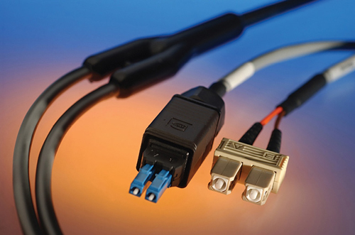
A preassembled fiber-optic cable using Fast BUS can control wind-turbine blade positioning.
Meeting such challenges make wind turbines considerable investments so wind-farm developers are always looking to reduce costs. What’s more, the critical nature of communication within the turbine makes it difficult to find ways to minimize costs. The only two options are to use lower quality cables or use an alternative construction of the pre-assembled unit. In the short-term, low-cost cables may look advantageous, but long-term costs, such as non-routine maintenance and replacement parts, make it an expensive route. Finding ways to keep costs at a minimum is important, but cutting back on data communication, the Achilles’ heel of the wind turbine, should be the last place to look for cost savings. WPE
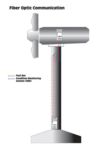 Pitching with a Fast BUS
Adapting the blade position in a timely manner to meet surrounding conditions is the object of a fiber-optic cable using the Fast BUS brand. Therefore, it’s generally preferred to use a fiber-optic cable with hard-clad silica 200/230 μm, Multimode (MM) G50/125 μm or MM G62.5/125 μm fiber types. The condition monitoring system (CMS) is the optimal way to measure and analyze a wind turbine’s operating characteristics, such as swing (a vibration or moving material which may cause damage to the turbine or tower) and push impulse sensors, lubrication data, and thermal indicators, whether on or offline. Monitoring centers evaluate the measured data of all plants using extensive analyses and compare them with reference data. The plant manager then receives verified fault messages along with an assessment of the current operational relevance, and specific action recommendations. Most of all, control systems specify a multimode fiber cable with G50/125 μm and a G62.5/125 μm fiber types.
Filed Under: Cables & connectors, Featured, News


Good share, if the wind turbine want to running normal, reliable data and power is very essential, especially for the data and communication cable, is is the connector between the control system with the turbine, because the special environment, the requires to the cable was very high, fiber optic and bus cable is a good choose. In additional, the wind turbine is the necessary parts in wind system.
More details: http://www.arslipring.com