Mark Barnes, VP of the Des-Case Lubrication Transformation Services, Des-CASE

Author Mark Barnes
Due to the high cost of replacing a failed gearbox up-tower, not to mention production losses, it’s no surprise that wind turbine manufacturers and operators alike have a keen interest in gearbox reliability. And while lubricant formulation has been a major focus of lube suppliers, controlling contaminants in a lubricant, such as particles and moisture, can have a significant effect on gearbox life and so has received significant attention.
Gearboxes in wind turbines differ from those in high-speed machinery. In ground-based gearboxes, the progress of failure can occur in weeks, days, or even hours. In wind turbines, the impact of contaminants on slower turning gear drives is slow and insidious. Nevertheless, the mean time between failure (MTBF) for gears and shaft-support bearings can be increased by as much as two to three times by maintaining optimum levels of fluid cleanliness and dryness.
We often treat lubricant selection and contamination as separate issues with separate failure modes, but in fact, they are linked. The reason for this can be explained by a simple graphical representation of a lubricant referred to as the Stribeck Curve. It is derived from Stribeck equation:
F = (ZN) / P
where F = friction, Z = oil viscosity, N = rotational speed, and P = load
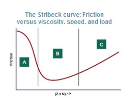
The Stribeck equation plots bearing friction versus load, speed, and lubricant viscosity. The curve also describes three operating regimes.
The classic Stribeck curve shows the relationship between friction and a bearings operating condition (ZN/P), and while it helps understand the concept of hydrodynamic lubrication in plain bearings, it also helps understand what can happen in a wind-turbine gearbox, particularly where sliding motion as well as rolling contact occurs.
The curve suggests three basic operating regimes. For a bearing at rest (N = 0), the operating condition is to the far left. As the bearing, or in this case gears, start to turn, speed (N) is low, load (P) is high, and because we use high-viscosity fluids in gearboxes, Z is also high. At slow speeds gears will be operating in the “A” condition, referred to as boundary lubrication.
Under boundary lubrication, the specific film thickness as defined by the average separation between moving parts is less than the surface roughness of the mating components. This is particularly true for gears and shaft support bearings on the low-speed end of the gear drive where speeds are lower and hence operating well to the left of the Stribeck curve. Under these conditions, it’s vital to use wear preventing additives in the oil, hence the reason for extreme pressure additives in wind-turbine gear oils.

The plot illustrates the relationship between lubricant cleanliness and equipment life. The X-axis is graduated with oil cleanliness values from ISO 4406:99. Values for dirty oil are on the left and for cleaner oil on the right. Hence, cleaner oil leads to a longer service life.
At higher speeds, the operating condition transitions from boundary to the B regime, referred to as mixed film. Under these conditions, the specific film thickness and surface roughness are about equal. This is the minimum speed for the applied load and viscosity for which true metal-to-metal separation occurs. Under mixed-film conditions, we still require good lubricity to counteract the occasional metal-to-metal contact, but wear rates are significantly lower than under boundary conditions.
The last regime is full film. Under full-film conditions, there is complete separation between moving surfaces inside the machine, with the only source of friction from internal fluid friction, as discrete oil molecules rub against each other.
While lubricant formulation and its role in the Stribeck curve is important, equally important is how contaminants interact at the different regimes of lubrication. The role of contamination in lubrication is two-fold. The first is the direct impact of contaminants. In sliding contacts, particles can become trapped between moving surfaces. As these surfaces move relative to each other, the particle acts as a tiny cutting tool, removing surface materials from one or both surfaces. This wear mode is known as 3-body abrasion. This is particularly prevalent under mixed film and boundary-lubrication regimes.
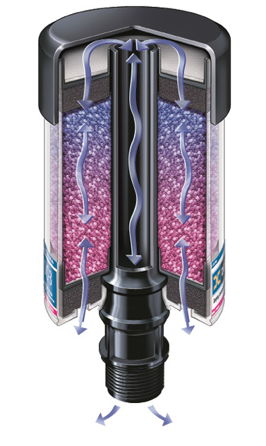
A conventional gearbox breather filter traps water entering and leaving the gearbox with a silica gel.
Under pure rolling contact, the presence of contaminants serves to concentrate and localize forces in the load zone resulting in Hertzian stress and eventual fatigue failure. Both 3-body abrasion and particle-induced-fatigue failures can be considered pure particle induced failures.
But there is also an insidious effect of contaminants in wind-turbine gearboxes, caused by other failures modes. Because most failure modes generate wear debris for long periods before outright failure occurs, the wear particles pass through critical clearances creating secondary wear. And while the particles are not the true root cause of the failure, we cannot overlook the effect that the generated material has inside the gearbox. In fact, studies from other industries have revealed that in “clean systems” only 7% of all particle matter is metallic, while in dirty systems, as many as 42% of all particles are metallic, indicating that any wear producing failure mode will induce secondary failure modes due to 3-body abrasion.
In understanding the impact that contaminants have, it’s important to understand the typical size range that causes the most damage. For the human hand to feel a particle as “gritty”, it must be at least 100 to 200 microns. A particle visible to the naked eye must be at least 40 to 60 microns in size. But, particles 10 micron and smaller cause the most damage in gearboxes. This stands to reason when we consider that typical dynamic clearances in a gearbox range from a few tenths of a micron to around 5 to 10 microns, depending on load, speed, and design. Particles in the 1 to 10-micron size range are often referred to as “silt-sized” particles.
To illustrate the effect silt-sized contaminants can have on life expectancy; consider the graph Relationship between fluid cleanliness in gear oil and life expectancy. It shows the effects of fluid cleanliness as measure by the ISO 4406:99 solid contamination code on life expectancy. For many industrial gear drives running in typical plant environments, the level of fluid cleanliness is often at or around 22/20/17 (c) or dirtier. This is particularly true where older style combination breather-fill caps or dipsticks, or both are in use. Based on the data presented in the Stribeck plot, by maintaining fluid cleanliness at or below the optimum levels of ISO 18/16/13 (c) or cleaner, the life expectancy of the gears and other oil-wetted components of the gear drive should be at least twice as long.
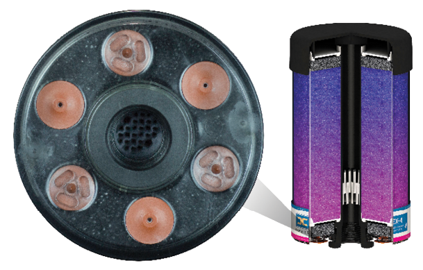
Depending on application and environment, these so-called hybrid breathers can last as much as 5 to 10 times the life of a conventional desiccant breather.
For water, a similar relationship holds between the level of contamination and the mean-time-between failure. While the hygroscopic nature of oil makes it next to impossible to keep gear oil completely free from water, keeping water at or below the saturation point is key. The saturation point for many conventional gear oils, at typical gearbox operating temperatures ranges from 400 to 600 ppm of water (0.04 to 0.06% by volume). For a gearbox that holds about 20 liters (5 gal.) that equates to as little 7.4 ml (1½ teaspoons) of water. Exceeding the saturation point lets water come out of solution into either the free or emulsified state. In this condition, the deleterious effects of water — which include loss of film strength, rust, and corrosion — increase exponentially, seriously impacting equipment life.
This problem is most pronounced in gear drives that operate intermittently at low ambient operating temperatures. While 500 ppm of water in a gearbox operating at 140°F (60°C) will typically all be in the dissolved phase, shutting down the gearbox and allowing the oil to cool to 32°F (0°C) will cause most of the water to come out of solution.
Water also has a secondary effect on gear oils. Many of the additives used in gear oils are either water soluble or react with water. As such, whenever gear oil is left saturated with moisture either due to an extended shut down period or from inappropriate new oil storage, additives can be stripped or rendered ineffective. For most gear oils, water levels must be kept dry enough so that any water that may be present is completely dissolved. While not possible in some circumstances, practical limits for water in gear oils should be less than 200 to 300 ppm (0.02 to 0.03% by volume).
Gearbox contamination control
Controlling contaminants within gear drives requires a concerted effort to assess each possible ingression source. With any contamination control strategy, the first place to start is to look at external sources of ingression. Most external contamination ingression in wind-turbine gearboxes comes from the breather or vent port. Because of the nature of the up-tower environment, most OEM’s require the use of a desiccant breather. These include a particle-removal element capable of eliminating silt seized particles and a desiccating media – often comprised of silica gel – to remove all traces of moisture from the air as it enters the gearbox. This type of breather provides bi-directional water removal. As the gearbox cools, for example, during a shut down, it draws air in and passes it through a foam element to dissipate air flow across the silica gel media. As the moisture laden air passes through the silica gel, moisture is absorbed by the silica gel. As the air exits the silica gel desiccant bed, the air also passes through a high efficiency particle removing media that removes all silt sized particles before passing down the central standpipe into the gearbox.
When air flow is reversed, for instance during gearbox start-up and warm up, the expanding air passes in the reverse direction causing the headspace of the gearbox to purge moisture and humidity that may have built up during shut down. By impregnating the silica gel with an indicator sensitive to the degree of moisture saturation, the change out interval for a desiccant breather can be optimized simply by observing the color change within the desiccant.
This is a helpful indicator for when to change the breathers and as a predictive or diagnostic tool. With the air flow shown in the breather illustration, a color change from the bottom up is indicative of moisture ingress from the environment, while a color change from the top down indicates internal moisture perhaps caused by another ingression source such as a defective shaft seal.
While standard desiccant breathers are effective at preventing particle and moisture ingress, their life can be relatively short, depending on the operating environment. To counteract this, desiccant-breather manufacturers have developed vented breathers. The advantage of this breather style is that unlike standard desiccating breathers, the system is nominally sealed, preventing contamination ingress and preserving the life of the breather. Depending on application and environment, these so-called hybrid breathers can last as much as 5 to 10 times the life of a conventional desiccant breather.
Equally important is the silica gel in the breather. Unlike its role in a standard desiccating breather, this silica gel in the hybrid breather is intended to dehumidify the headspace in the event that moisture enters the gearbox from other sources. Dehumidifying the headspace helps keep the oil free from water due to effects of Henry’s law which governs the relative humidity of the air-oil interface.
Kidney loop filtration
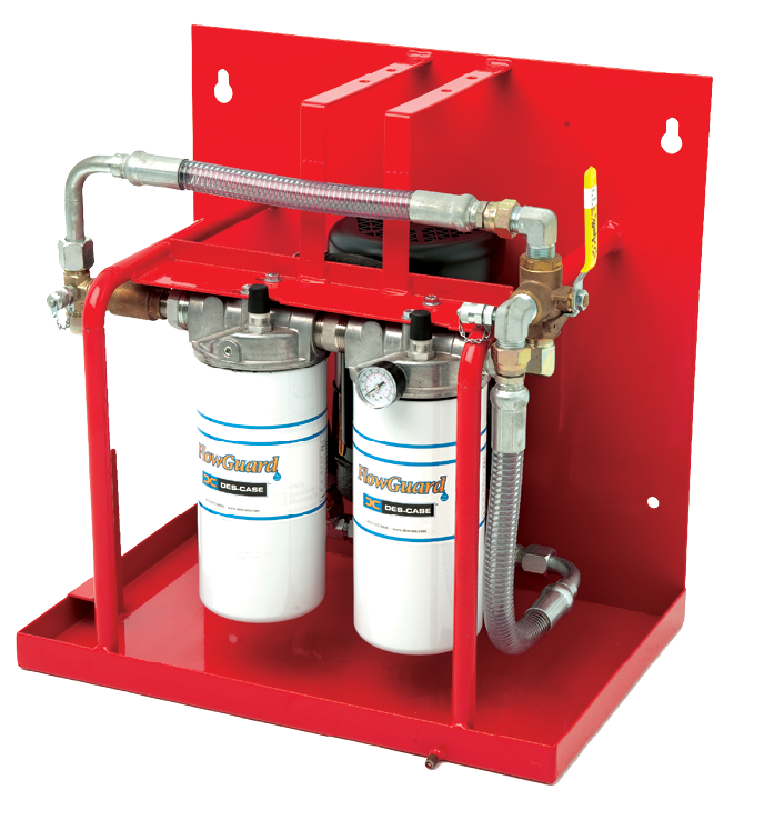
A kidney-loop filtration system of this sort is well suited for work on wind turbine gearboxes.
While a desiccant breather is an important first step, installing permanently mounted dedicated filtration systems are vital to eliminate particle-induced failures from internally generated particles. Just as a kidney dialysis machine removes hazardous impurities from the blood, kidney-loop filtration systems take the lifeblood of the gearbox – the oil – and removes particles and moisture before returning it to the oil sump. Ideally, the filtration system should allow both particle and moisture removal, and have good particle capture efficiency to optimize the time between necessary filter changes.
Given the importance of production and the penalty of replacement costs, it’s vital that wind turbine gearboxes remain reliable throughout their life. Properly lubricated with a strong focus on both ingressed and internally generated contaminants, lubrication related failure can be easily avoided with a few simple precautions. 
Filed Under: Filters, News, O&M