Ashley Crowther, VP Engineering, Wind Romax U.S.
A case study shows how condition-monitoring data and engineering analysis can identify the root cause of trouble in wind-turbine drivetrains, and then give design teams information to solve the problems.
Maintaining profitability is one of the biggest challenges facing offshore wind-farm operators and owners. Innovative technology and logistics mean reliability issues and traditional reactive-maintenance practises lessen viability of equipment mounted offshore.
To meet these challenges, wind-farm owners and operators are turning to “asset management” companies along with operations-and-maintenance (O&M) suppliers to reduce the cost of running the turbine fleet. As with any fledgling industry, offshore wind is bound to suffer from teething problems. Drivetrain failures are responsible for a significant amount of turbine downtime, particularly in the gearbox and main bearings.
Why repairs fail
There are 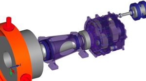 many reasons these major components suffer. Most of their performance shortcomings stem from extreme weather conditions, manufacturing errors, and sometimes fundamental design flaws. Surface fixes, such as bearing or gearbox replacements, often prove to be short-term fixes and fail to find a root cause. Superficial repairs lead to repeat failures and additional cost.
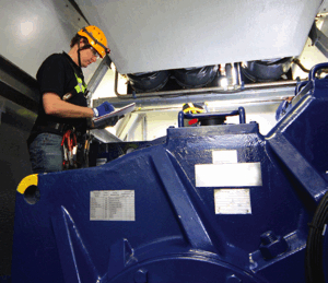
The tech records a few maintenance figures in a nacelle. The size of the gearbox shows that almost any repair to it will require heavy-duty labor.
Mitigating such risk requires an in-depth understanding of the complex drivetrain system and environmental interactions, something which only experienced wind-energy providers and technical experts can provide. Drivetrain assessments, component-life predictions, and end-of-warranty inspections form part of an O&M program that can reduce cost and increase reliability.
A good example of how these services can improve turbine reliability and safeguard future wind farm profitability is a recent project conducted by colleagues at an offshore wind farm. The project set out to identify the cause of an unusual number of identical failures in the turbine fleet. The operator also wanted to understand the nature of the vibration characteristics uncovered by their condition-monitoring data, and whether those signatures were indicative of a wider reliability issue.
A failure distribution analysis found that 80% of the particular failures were due to bearings, and nearly 10% due to gears. The bearing-failure ratio was much higher than other farms in the fleet, especially for the high-speed shaft bearing which was a problem for the turbines in that series. The engineering analysis team had to establish the root cause of the high-speed shaft bearing failure.
An assessment of vibration data showed that the high-speed gear mesh’s 3rd harmonic and oil pump’s 6th harmonic had high amplitudes near the machine’s rated speed and power.
When the machine speed decreased, these vibration amplitudes reduced markedly, but the high-speed gear mesh 4th harmonic grew in magnitude. Field data showed that at rated speed and power the two vibration sources (high-speed gear mesh and oil pump) where contributing 40% of the RMS vibration level of the gearbox. Assessing data from other turbines in the fleet showed the vibration issue in all gearboxes of the same make and pointed to a serial design problem.
To carry the investigation further, the team built a simulation model of the gearbox in RomaxWIND software to predict the structural vibration response from the gear transmission error and its multiple harmonics. The software is a simulation tool with capability to model an entire gearbox (gears, carriers, bearings, lubricant, and housing) and predict dynamic behaviour under particular operating conditions –certain torques and speeds. It is applied to wind farm, drivetrain-issues in combination with practical engineering design and field work.

LEFT: A gearbox simulation showed several modes that will be excited near 1,600 rpm. The image shows one example, a bending mode of the high-speed shaft. The model can be used for gear-tooth microgeometry optimization, one way to reduce the vibration level. CENTER: Data for the charts came from a different wind farm than the one in the case history. The top pie charts shows turbines there have trouble about 59% of the time because of gearbox failure, and those most often because of bearings, and that most bearing failures occur on the high-speed shaft. RIGHT: A wind turbine gear box has been modeled in Romax Wind, modeling and simulation software for wind turbine drive trains and pitch and yaw systems. A transparent housing shows two planetary stages and their arrangements.The high-speed output shaft appears to the lower left with the output torque designated as a red ring.
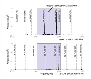
The vibration spectra plots vibration amplitude versus frequency for two shaft speeds. At 1,698 rpm on the output shaft, the oil pump’s 6th harmonic and the high-speed shaft’s 3rd harmonic dominate. Dropping the shaft speed to 1,296 rpm also drops amplitudes of the two components while the 4th harmonic on the high speed shaft dominates. This indicates something amiss with the high-speed shaft.
The software’s dynamic analysis demonstrated that subsystem resonance at rated condition was the likely cause. The Waterfall graph shows a predicted housing response for the first three harmonics of the high-speed gear mesh. The resonant behavior of the system with the 3rd harmonic from 1,600 to 2,000 rpm is also evident. Correlating to the vibration characteristics from field data helps then to use the model to understand the source. In this case, many local structural modes are excited by the HS gear and oil pump higher harmonics. The illustration Bending Mode shows an example bending mode that will respond to the excitation.
The analysis uncovered several issues contributing to the poor bearing reliability, one of which is a serial issue of resonance of gear excitation frequencies with the structure. By simulation and field work, the analysis team demonstrated that the gearbox had not been designed for good vibration characteristics at operating torque and speeds. In addition, the technical team was able to explain how design improvements could overcome these issues.
For a gearbox retrofit, it is not practical to change the structure and shift the resonances. Hence, practical engineering solutions include investigating the surface waviness of the oil-pump gear from manufacturing processes to ensure it is not related to the 6th harmonic, changing the number of gear teeth on the pump, or improving the microgeometry design.
For the high-speed gear, a good avenue for improvement would be microgeometry optimization to reduce source excitation; the third harmonic of the gear transmission error. Microgeometry optimization could include parameters such as tip relief, root relief, and involute crowning and would need to be engineered so modifications do not reduce gear durability.
By redesigning the component, the turbines would be able to run more effectively. Of course, gearbox rebuilds must be kept within design and cost constraints and they certainly should not go back to the field with the same problems.
Understanding flaws
The analysis team showed that by understanding faults and the ability to predict the lifespan of components through simulation, wind-farm operators can greatly improve their knowledge and ability to schedule maintenance for their fleet of wind turbines. Much of Romax’s field engineering focuses on this issue because a reasonable bottom line for the fleet depends on improving reliability and controlling costs.
A proactive approach to turbine fleet management can have a significant impact on the running costs and fleet uptime. The ability to feedback potential design issues through the manufacturing cycle also significantly aids in the design of new machines and helps ensure the next generation of turbines is installed without the problems of the past.
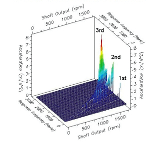
Housing response to high speed gear vibration: High-speed shaft speeds plot on the X axis (rated speed is approximately 1,600 rpm for this shaft). Vibration amplitude plots on the Z axis, from the gearbox housing near the high-speed shaft. And response frequency plots on the Y axis. It’s the frequency of the actual vibration of each harmonic at a certain shaft speed (X axis speed). As the gearbox speeds up, vibration at the 3rd harmonic grows to a resonance near 1,600 rpm and then falls away again as the machine runs faster. The high-speed gear is the largest contributor to vibration.
WPE
Filed Under: Featured, O&M




Can I just say what a relief to find http://www.windpowerengineering.com who actually knows what theyre talking about on the internet. You definitely know how to bring an issue to light and make it important. More people need to read this and understand this side of the story. I cant believe youre not more popular because you definitely have the gift.
It’s a bit surprising that the original designers of the gearbox did not do a check of meshing and forcing frequencies against the structural modes of the rotating components. In my experience, one would check each component’s first 8 or 10 modes. If a coupled mode was found in a particular gear mesh, the meshing frequency can be shifted by altering the tooth counts and DP without changing the gear pitch centers.
The most common problems I’ve seen in wind turbine gearbox designs are lack of strain isolation from the rotor moments, poor load distribution across the gear faces due to high L/D aspect ratios, and poor load distribution in rolling element bearings due to high L/D ratios in the rollers vs. the gearshaft/housing deflections. Looking at the example shown above, you can see the gears meshes that are giving trouble (the 3rd stage and lube pump drive) have the combination of high L/D gears and small diameter bearings.
Gear tooth microgeometry optimization (ie. tip mods, involute profile mods, lead correction, reduced index errors, reduced PL run out, and face profile mods) can make a good gear better, but it will not make a bad gear good. With the sophisticated digital analytical tools available today, such as those marketed by Romax, there is no excuse for having these types of issues in a gearbox design.
what was the solution to the problem?
Mr. Bernhardt:
Thanks for the question. Author Crowther says:
For a gearbox retrofit, it is not practical to change the structure and shift the resonances. Hence, practical engineering solutions include investigating the surface waviness of the oil-pump gear from manufacturing processes to ensure it is not related to the 6th harmonic, changing the number of gear teeth on the pump, or improving the microgeometry design.
For the high-speed gear, a good avenue for improvement would be microgeometry optimization to reduce source excitation; the third harmonic of the gear transmission error. Microgeometry optimization could include parameters such as tip relief, root relief, and involute crowning and would need to be engineered so modifications do not reduce gear durability.
By redesigning the component, the turbines would be able to run more effectively. Of course, gearbox rebuilds must be kept within design and cost constraints and they certainly should not go back to the field with the same problems.
Are the drivetrain problems associated with wind turbines similar to the ones we see in automobiles?
When the drivetrain problem is resonance from a vibration or rotating source, yes.