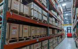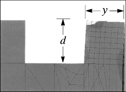
Finite-element analysis shows stress gradients for a retaining ring in an application with insufficient edge margin. When loaded, the high-stress region extends over the entire groove wall to the shaft end (or housing end) distorting the groove wall. Under these conditions, the ring would buckle, possibly leading to catastrophic failure.
The manufacturer of retaining rings, hose clamps, and related products recently published formulae on its website (www.rotorclip.com/formulas.php) for determining thrust loads and tolerances, and avoiding costs associated with over-estimating application requirements.
Maximum allowable thrust load capacities for all retaining rings are given in the manufacturer’s technical manual. Design engineers can use this information to determine if their application requires a ring suited for withstanding thrust loads or static retention. There is no need to design in one type when another will do at a lower cost.
For example, consider an assembly onto which components must be fastened in a bore or housing 0.750-in. dia. A self-locking retaining ring, which does not need a groove, provides 66 lb of static thrust-load capacity. An external retaining ring for the same application installed in a soft groove provides 1,200-lb static-load capacity with a safety factor of two. If the application’s load capacity is 66 lb or less, the self-locking ring presents the most economical and effective approach to meeting the fastener requirement.
Rotor Clip Company Inc.
Filed Under: Components