How difficult can it be for a hard-composite turbine blade spinning at a leisurely 15 rpm to last 20 years? Considering that blade tip can be slicing the air at 150 mph and the air may be filled with sand, grit, bugs, hard driving rain, and the occasional hail, functioning well for 20 years becomes a considerable accomplishment.
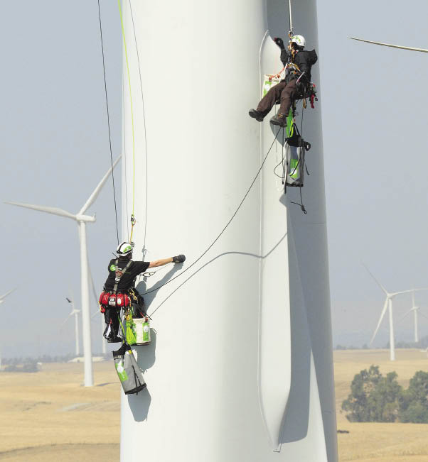
A Rope Partner crew works near a blade root on a REpower machine. The fin to the right is a spoiler, an aerodynamic feature that improves blade performance. The crew inspects and repairs the turbine blades. The rings around the blade are fences, features that direct wind flow. Photo: Dennis Schwartz
Blades take a lot of abuse. Most maintenance focuses on the quality of the leading edge which affects lift. If the leading edge does not have the right shape, the turbine loses power and misses potential. To handle airfoil problems, maintenance companies are developing a range of skills and lift improvements.
Fixing fouled airfoils
“Leading-edge erosion is the biggest problem with airfoils not performing as well as when they were new,” says Chris Bley, Business Development and R&D at Rope Partner (ropepartner.com). “When you notice erosion from the ground, it has reached an advanced stage of decline.” Erosion can reach through the topcoat into the fiberglass material below. So when it is bad enough to be seen at a distance, it’s past the time for a simple solution. Bley says looking at blades up-close reveals many smaller cracks and delaminations that go unnoticed from the ground. In cold environments, water can then get into cracks and freeze, enlarging the problem. The key to preventing serious blade issues is to detect surface damage early and resolve it.
It’s hard to predict how blades will wear because manufacturers use different materials, construction, and aerodynamic designs. Bley says that environments also affect blade wear. “If you start with a durable leading edge or leading-edge protection installed at manufacturing and an environment with little erosion, you might not see a problem for the life of the turbine,” he says. “On the other hand, if the blade has a softer material, no leading-edge tape, and the turbine is working in an area with a lot of salt or dust – such as West Texas where there is greater leading edge erosion due to dust in the air–you have bigger problems sooner.”
The hydraulic affect of the rain hitting the blade tip can also cause erosion because it’s moving upwards of 150 mph. Bley says hydraulic forces are sufficient to push water into the smallest of openings.
A wide range of blade designs means service companies are challenged with a range of maintenance tasks. For instance, a maintenance firm should be familiar with the variety of composites and other blade materials, architecture, and construction methods used to build the many different varieties and generations of wind turbines. This is quite challenging to keep up with, even when focusing on turbines coming out of warranty. Owners of these machines suddenly require additional outsourced support to understand and care for their blades necessitating careful selection of a maintenance partner to combat these challenges.
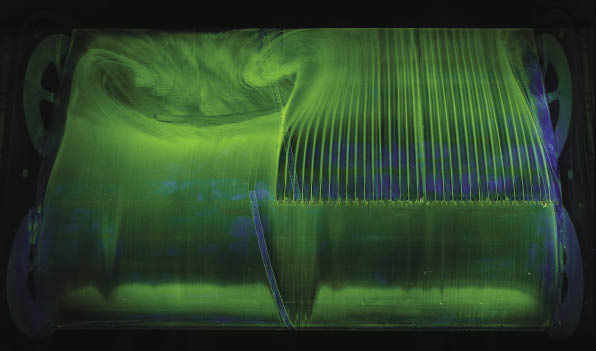
The image was taken by engineers at LM Wind Power during a wind-tunnel test. Vortex generators span the right side of the airfoil segment. Streamlines indicated almost laminar flow across a large section of blade while turbulence is visible on the left.
Maintenance step one
“A maintenance firm should identify the problem and a solution that will bring the performance up to what is expected,” says Rob Kamisky, CEO of WINDprove (windprove.com). He says the company consults with owner-operators to help them find out why performance may be dropping off. That might require blade inspections by Rope Partner teams to see if blade condition is the problem. Once a diagnosis is complete, a solution can be implemented. For instance, blade enhancements or modifications could be helpful or just repairing and protecting a leading edge with tape or coating.
Another way to identify problems with turbine performance comes from examining SCADA data. In one case, says Kamisky, examination of SCADA records following a tip strike led to the discovery of an error in the blade pitch settings for the entire park. Photographic analysis was then used to determine the correct pitch setting for each turbine.
Kamisky says he formed WINDprove to manage collaboration among a variety of engineering disciplines that have been active in the wind industry. “In the past, we were just a group of independent consultants. Now the company centralizes wind project management and works as a point of contact and administration for a larger group of consultants“.
OEMs may provide some blade modifications such as spoilers or dynofins, a serrated edge that some say improves air flow. An accompanying photo shows what appears to be a hump or fin near a blade root. The fin is a spoiler, an aerodynamic feature some blade manufacturers use to increase power output.
Vortex generators
To better understand blade aerodynamics, Kamisky recommends studies in wind tunnels or CFD simulations of proposed blade attachments. “We look at the blade in two configurations,” he says. “One is perfectly smooth without interruptions in the flow. The other has conditions that produce a flow disruption on the surface – something to induce a separation or turbulence of flow around the blade.” This might be surface roughness in the form of leading-edge erosion or a buildup of debris, or bugs.
One concept for restoring performance to wearing blades comes from the aircraft industry and is getting a lot of attention in wind. Vortex generators (VGs) have been used since the 1940s and are visible on modern passenger aircraft wings. They appear as small rectangles placed along the wing’s crest. When used on a wind turbine blade, VGs generally provide greater output for the turbine.
Vortex generators have been applied to wind turbines several times over the last 20 years with varying degrees of success. One area where they’ve been helpful is in combatting flow separation. Kamisky explains this is when the flow, usually moving smoothly along the airfoil, separates at some point so it’s no longer attached and predictable. The VG sort of steers the low momentum air away from the blade and brings high momentum air back down to the surface which re-energizes the flow and reduces flow separation. Kamisky says this can gain back some rotor performance losses caused by flow separation. “But it is important to look at the effects on turbine loads and performance before adding VGs,” he says
Bley’s team is occasionally tasked with putting VGs on blades. “We install and maintain them. For example, if blade ice shears off, it could take the VG off as well,” he says.
Rope Partner works with groups such as WINDprove, which are more involved with design and placement of the VGs. “We are the brawn behind the equation.” says Bley. “Companies such as WINDprove provide the analysis to increase the efficiency of airfoils. Such companies know what size of vortex generators to use, their design, and where to place them, while Rope Partner installs them in a safe, efficient, and cost effective manner. Bley says it’s important to put VGs in the right location and makes sure they are attached correctly. Measuring positions and identifying a correct orientation, however, is challenging because blade surfaces curve and the leading edge slopes at different diameters. “It’s quite a challenge because the position tolerance is small,” he says. The time required to attach VGs varies depending on coverage, but typically, two blades of one turbine can be installed in a day.
R&D
Although vortex generators hold promise as a power improver, they deserve a word of caution. “Vortex generators are still a research project,” says Case van Dam, Chair of the Department of Mechanical and Aerospace Engineering at the University of California, Davis. “They are pretty difficult to quantify on a single wind turbine because their effect is dependent on the type of turbine and even the site,” he says. The amount of improvement provided by VGs varies. Blade manufacturer LM Windpower claims a 4 to 6% boost. One owner-operator has installed many VGs on its 1.5-MW turbines but data is still being collected. “Experimenting with VGs is not something to take lightly,” he says. “It can be time consuming and small differences in VG placement can significantly affect the findings.”
Van Dam and his group at the University also work with Sandia National Laboratory on advanced blade designs. The program involves wind tunnel testing and CFD simulations, so in the process Van Dam has looked at blades and aerodynamic concepts, such as VGs, along with smaller strips and fences. He says crews nowadays are more sophisticated, so instead of just adding something to a blade, they do a technical analysis first based on published data, along with the wind-tunnel tests, and simulations.
Van Dam cautions about putting VGs on a clean new blade because they will probably handicap it, resulting in less power production. But when a blade soils or its surface erodes, the aerodynamics are suddenly not as they were. The blade has deteriorated to a point where the flow separates. VGs become a simple way to reduce the flow separation.
Then there is the issue of aerodynamic noise. “Separated flows create more noise and, hence, VGs might reduce noise,” says Van Dam. “The unfortunate thing in this industry is that Siemens and other VG users do not talk much about the analysis on which they base these modifications. So you just have to do some head scratching and ask ‘why are they putting them on?’ Sometimes companies put them on, find out that they don’t do much, and then leave them on anyway because they confuse the competition.”
Vortex generators are not the only concept that comes up a lot in discussions. “About a year ago everyone wanted to put winglets on turbine blades, but that has died down,” Van Dam says. “Sometimes people in the industry see a new thing and think, ‘OK if the competition is doing this, we must move forward on a similar effort.’” He also sees changes in the airfoil design for turbine blades – efforts to get more aerodynamic performance from them – but at the same time making them less sensitive to soiling and erosion. When performance drops sufficiently, VGs may mitigate the performance loss.
VGs, however, are not the last word in blade modifications. One idea in development, smart blades, carry load sensors and active surfaces to capture the maximum power from any wind speed. And even those are just one of several introductions that will challenge maintenance teams all the more. WPE
Filed Under: Blades, Turbines




I am disappointed to see that you’re confusing turbulent flow and separation. Any large turbine blade that has bugs on it or uneven erosion will have a turbulent boundary layer anyway. A laminar boundary layer doesn’t have much mixing. A molecule of, say, nitrogen that is 0.1mm from the surface, near the leading edge, will still be a comparable distance from the surface near the trailing edge. And, since it’s deep inside the boundary layer, it will be moving pretty slowly. Unless there is separation, in which case it’s likely to be a LONG way from the surface. On the other hand, in turbulent flow, the boundary layer is still attached, but that molecule might end up much further or a bit closer by the time it gets near the trailing edge.
It is my understanding that vortex generators bring higher velocity air near the surface, which makes the flow stay attached to the surface better.
THe following pictures and explanation should make a bit clearer the difference between separated and turbulent flow:
http://www.efluids.com/efluids/gallery/gallery_pages/wake_page.jsp