A main lightning discharge is characterized by rapidly rising current that peaks at about 200,000 Amps and averages about 30,000 Amps over its duration. Even though the event is over in milliseconds, there is great potential for harm to personnel and damage to equipment. Personnel working around such a hazard that often strikes wind turbines want to know that they are safe when entering a tower. Electrical grounding is the foundation for an expected level of safety and that begins with a properly designed and installed electrical grounding system.
A designer of such equipment must accept two major goals for the operation of a safe wind-turbine ground system:
• Assure that people in the vicinity of the grounded facility are not exposed to the danger of electric shock
• Provide a means to dissipate electric currents into the earth without exceeding the equipment’s operating limits.

CADWELD Welded Electrical Connections provide a permanent molecular bond that will not loosen or corrode over time. This helps to create a long-lasting, reliable grounding network. In addition to grounding equipment, ERICO engineers can provide design assistance for grounding and lightning protection.
One expects a grounding system to work after commissioning a farm, but what about its longterm reliability? A good grounding system that dissipates lightning current and clears faults quickly helps improve the overall safety and reliability of an electrical system. Reliability must be “built and installed” from the start of the project.
Furthermore, design and material requirements should become more stringent as OEMs build larger structures with greater power outputs. Design considerations for a wind turbine’s grounding system should include:
• Initial soil resistivity tests. These provide a basis for the design.
• A ground-grid footprint and geometry tell how much area there is to work with.
• Line-to-ground fault current specs.
• Specified design resistance of a ground grid. This is often in OEM product specifications and warrantees.
• Possible hazards to individuals working in electrical substations, including stepand- touch potential effects of a Ground Potential Rise (GPR). IEEE Standard 80 defines GPR as a maximum electrical potential that a substation grounding grid may attain relative to a distant grounding point assumed to be at the potential of remote earth. This voltage, GPR, is equal to the maximum grid current times the grid resistance. Step potential voltage is the difference in surface potential experienced by a person bridging a distance of 1 m by foot without contacting any grounded object. And touch voltage is a potential difference between the ground potential rise and the surface potential at a point where a person is standing while touching a grounded structure.
• Materials
• Quantity of buried conductor and ground rods
• Bonding to the foundation rebar and anchor bolts
Site location, the first point, often involves areas of high soil resistivity. In addition, the increased height of more recent wind-turbine designs makes the threat of a lightning strike more likely. Although soil and height make it difficult to design a low impedance grounding system, designers must consider their importance at every wind turbine.
Wind farms consist of interconnected low voltage electrical apparatus and mechanical equipment to form large electro-mechanical systems. Although there are inherent operational dangers, the systems are intended to operate without danger when appropriate routine procedures, and suitable tools and work equipment are correctly used. The purpose of grounding equipment is to maximize the surface-area contact with soil. Lowering the resistance and improving the surge impedance of the grounding hardware helps dissipate a lightning impulse that has a fast-rising edge and a high fundamental frequency, while minimizing the ground potential rise. A typical waveform associated with the lightning impulse reveals high and low-frequencies. The high frequency is associated with the fast rising “front” (typically < 10 μs to peak current) of the lightning impulse, while the lower frequency component resides in the long, high-energy “tail” or follow-on current in the impulse. The grounding system appears to the lightning impulse as a transmission line.
Hence, wind-turbine grounding must satisfy three criteria:

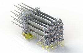
A wide variety of lightning protection conductors are available to help prevent damage to wind turbine blades.
• The system has to effectively dissipate the lightning energy.
• Provide sufficient ground-reference potential to assure the proper operation of the electrical equipment.
• Satisfy step-and-touch potential requirements for the safety of personnel.
Despite the importance of grounding system impedance, the grounding system is typically evaluated with measurements of low-frequency resistance. Many windturbine manu-facturers require a particular value for the resistance, such as 10 Ω for each turbine. This helps protect the generator and other sensitive electrical equipment, and honor a warranty for the whole wind turbine. This value is required even in high soil resistivity (over 5,000 Ωm) and limited space for a wind turbine’s grounding system. These variables work directly against each other.
Although a fixed footprint may make it difficult to meet a specified dc-resistance value, proper design can help maximize the efficiency of the grounding grid. A given area limits the amount of grounding equipment it can support. Therefore, grounding systems are typically treated on a case-by-case basis. Doing so provides an effective and economical grounding solution.
A grounding-system resistance of 10 Ω is sufficient for dissipating light-ning energy, but resistance for the power distribution system should be significantly lower, typically less than 5 Ω. Interconnecting the individual ground systems on each turbine greatly reduces the resistance for an entire grounding network.
Several international standards support the 10-Ω value for an individual wind turbine, but a safe wind turbine work environment still depends on site evaluation (resistivity testing) and proper design of the electrical-grounding system.

Rise (GPR). IEEE Standard 80 defines GPR as a
maximum electrical potential that a substation
grounding grid may attain relative to a distant
grounding point assumed to be at the potential
of remote earth. This voltage, GPR, is equal to the
maximum grid current times the grid resistance.
Step potential voltage is the difference in surface
potential experienced by a person bridging a
distance of 1 m by foot without contacting any
grounded object. And touch voltage is a potential
difference between the ground potential rise and
the surface potential at a point where a person is
standing while touching a grounded structure.
• Materials
• Quantity of buried conductor and ground rods
• Bonding to the foundation rebar and anchor bolts
Site location, the first point, often involves areas
of high soil resistivity. In addition, the increased
height of more recent wind-turbine designs makes
the threat of a lightning strike more likely. Although
soil and height make it difficult to design a lowimpedance
grounding system, designers must
consider their importance at every wind turbine.
Wind farms consist of interconnected lowvoltage
electrical apparatus and mechanical
equipment to form large electro-mechanical
systems. Although there are inherent operational
dangers, the systems are intended to operate
without danger when appropriate routine procedures,
and suitable tools and work equipment are
correctly used.
The purpose of grounding equipment is to
maximize the surface-area contact with soil.
Lowering the resistance and improving the surge
impedance of the grounding hardware helps
dissipate a lightning impulse that has a fast-rising
edge and a high fundamental frequency, while
minimizing the ground potential rise.
A typical waveform associated with the lightning
impulse reveals high and low-frequencies. The
high frequency is associated with the fast rising
Guiding 200,000 Amps safely to ground
A main lightning discharge is characterized by rapidly
rising current that peaks at about 200,000 Amps
and averages about 30,000 Amps over its duration.
Even though the event is over in milliseconds, there is great
potential for harm to personnel and damage to equipment.
Personnel working around such a hazard that often strikes
wind turbines want to know that they are safe when
entering a tower. Electrical grounding is the foundation
for an expected level of safety and that begins with a
properly designed and installed electrical grounding
system.
A designer of such equipment must accept two
major goals for the operation of a safe wind-turbine
ground system:
• Assure that people in the vicinity of the grounded
facility are not exposed to the danger of electric
shock
• Provide a means to dissipate electric currents
into the earth without exceeding the equipment’s
operating limits.
One expects a grounding system to work after
commissioning a farm, but what about its longterm
reliability? A good grounding system that
dissipates lightning current and clears faults
quickly helps improve the overall safety and
reliability of an electrical system. Reliability must
be “built and installed” from the start of the
project.
Furthermore, design and material
requirements should become more stringent
as OEMs build larger structures with greater
power outputs. Design considerations for
a wind turbine’s grounding system should
include:
• Initial soil resistivity tests. These provide a
basis for the design.
• A ground-grid footprint and geometry
tell how much area there is to work with.
• Line-to-ground fault current specs.
• Specified design resistance of a ground
grid. This is often in OEM product
specifications and warrantees.
• Possible hazards to individuals
Mike Gassman
ERICO
S o l o n , Ohio
e r i c o .com
CADWELD Welded
Electrical Connections
provide a
permanent molecular
bond that will not
loosen or corrode
over time. This helps
to create a long-lasting,
reliable grounding
network. In
addition to grounding
equipment, ERICO
engineers can
provide design
assistance for
grounding and
lightning protection.
Filed Under: Construction, Safety
This is a very well explained article. I would like to know the author’s contact info. My company supplies ground wire/cable which offers superior longevity and lower cost to common copper conductors/connectors. Who in your publication would be interested in furthering the education of your readership on how to reduce costs while optimizing ground systems for wind turbines?