Scott Eatherton
Scott Eatherton / CEO / Wind Driven LLC
Question: What is the quickest way to find the weak points in a mechanical design?
Answer: Install it in a wind turbine.
It’s not a joke. Load spectrums in wind turbines are unique. The wide variations in wind speeds produce wide ranges of shaft torque, nacelle motion, and faulting events that lead to high-frequency vibrations, impact loading, and torque reversals. So in addition to the fatigue modes of micropitting, axial cracking and spalling, the near constant changes in acceleration subject wind turbines to a well understood, highly destructive, yet little-recognized wear mode: Fretting corrosion.

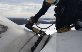
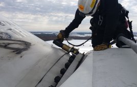
Look for fretting corrosion in these places in a wind turbine.
Fretting corrosion affects many critical wind turbine systems. It may be, in fact, their most common non-fatigue failure mode. Unlike the chemical corrosion of exposed external surfaces, fretting occurs in the contact zone of two or more parts under pressure. This includes bolted connections, gear teeth, roller bearings, and interference fitted parts.
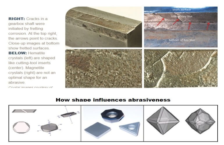
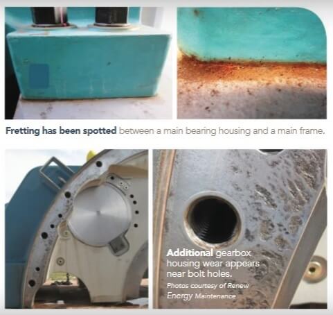
The four-panel photo illustrates the destructive power of fretting in a wind turbine (WT) gearbox. During disassembly of the failed gearbox, we unexpectedly found an additional failure. Several large cracks were found in the key slot of a shaft, initiated by fretting corrosion. This was an eye-opening experience. Ever since, I’ve been on the lookout for fretting corrosion, especially during warranty-sweep inspections.
Fretting corrosion occurs when:
• Two metal surfaces are in direct contact.
• Vibration causes minute repetitive oscillatory motion between the surfaces.
• Contact pressure sufficient to cause shearing-off of minute high spots during vibration.
• Oxygen is present, from the air or dissolved in lubricants.
The portable X-ray diffraction equipment (left) from Olympus has brought down the cost of tests for fretting corrosion. The equipment (left) shows the few tools and supplies required. The instrument provides a lot of information (right) but most important is that the sample is 55% hematite, 30% magnetite, and 15% iron.
Fretting also occurs in both lubricated and lubricant-free connections.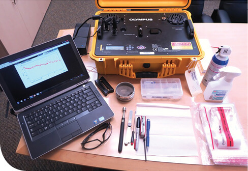
•
When a lubricant is present, fretting takes the relatively benign form of false brinelling. The tiny pieces of iron sheared from rough surfaces are oxidized. The particular species of iron oxide produced is magnetite, a black and highly magnetic material.
• When lubricant is absent, fretting corrosion produces hematite, a highly abrasive species of iron oxide. Hematite is a fine-grained, reddish to red-brown powder. It is used commercially to polish gems and is commonly known as jeweler’s rouge.
But what makes these two oxides of iron so abrasive, and why is hematite so damaging and magnetite relatively benign? The answer lies in the form of atomic bonding and the shape of the crystals.
Here we are concerned with two of the three forms of atomic bonding:
• Ionic bonding: Molecules and crystals form when atoms seeking to gain electrons meet atoms seeking to give up electrons. Most abrasives are ionically bonded compounds.
• Metallic bonding: Molecules and crystals form when metallic atoms all benefit by constantly shuttling electrons throughout the piece of metal.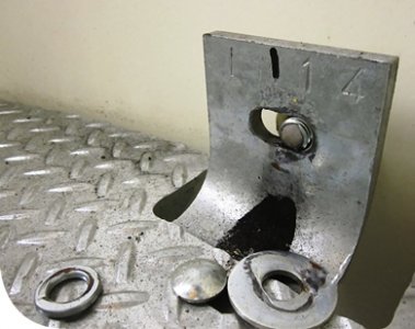
Ionic bonds are strong and highly directional, resulting in materials that are hard, extremely rigid, and strong. They are also inelastic, brittle and lack a toughness needed to resist cracking. These characteristics make ionic bonded materials self-sharpening, so when they break, rather than bend or deform, they form more sharp edges and corners. Contrast this with metallic bonds, which are strong but not highly directional. These result in materials that are hard, have elasticity, ductility, and toughness but are vulnerable to abrasion.
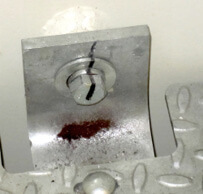
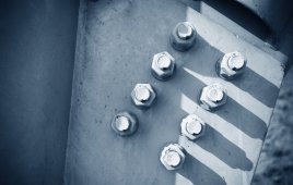
The yaw deck bolts have failed by fretting corrosion due to a design defect.
Both hematite and magnetite have a Mohs scale of hardness equal to a knife blade, about 6. The reason hematite is so abrasive lies in the shape of its crystal, as shown in the illustration How shape influences abrasiveness.
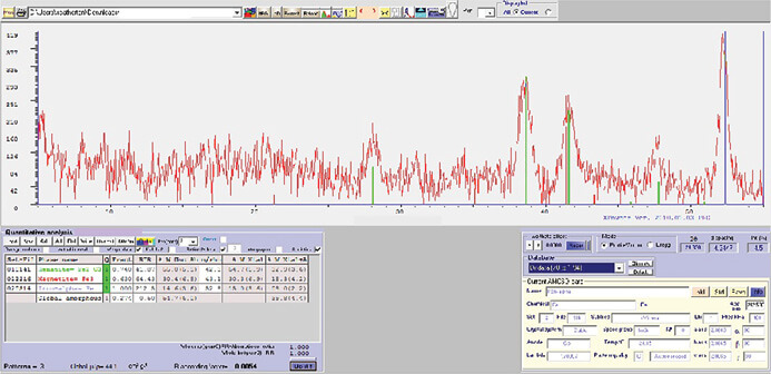
X-ray diffraction is the definitive method of identifying hematite and magnetite, for example, during a warranty sweep. The cost is currently about $750 per sample due to equipment. Recently, however, using technology licensed from NASA, Olympus has designed two relatively affordable products in bench-top and portable versions. These instruments are user-friendly and take only a few hours to master. The photo above shows the portable version in field use and the results of a WT sample analysis. The graph’s x-axis is the diffraction angles of X-rays from the planes in a crystal’s lattice that uniquely identifies a material. The y-axis is intensity. The vertical green lines indicate hematite, red is magnetite and blue line is iron.
The failed bolts on angle brackets provide more examples of fretting in WT components. In each case, fretting wears away material in the bolted connection. As material wears away, looseness increases and with it the rate at which fretting wears away material. Fretting is therefore often self-aggravating.
Bolts store elastic potential energy when torqued or tensioned. Longer and higher strength bolts store more energy and resist loosening from fretting. This energy is stored by elastically stretching the bolt by about 0.1% or 0.001-in. per inch of bolt length. Whether torqued or tensioned, the stored elastic energy is known as preload. This preload lets bolts withstand the highly variable load spectrum found in WTs. So consider: If fretting wears away just 0.005-in., a 10-in. bolt loses half its preload and will eventually fatigue and fail.
Here are a few methods for mitigating fretting corrosion in bolted connections:
• In newly installed WTs, re-tighten all critical drivetrain fasteners after a few hundred hours to compensate for relaxation in fasteners, the bolted components, and paint and coatings.
• Increase fastener torque. Use torque-tension calibration to avoid over-tightening and ensure that the torque used creates required preload.
• Use direct tensioning in preference to torquing.
• When torquing bolts, reduce the variability in their preload by using an anti-seize compound on threads. The torque required will be much lower than dry bolts. So to avoid yielding bolts use a torque-to-tension calibration tool.
• Use spacers to increase bolt length. Longer bolts reduce preload loss as fretting wears away material in a bolted connection, prolonging the life of bolted connections subject to fretting corrosion.
• Use friction shims to reduce the relative motion between mating surfaces, and thereby the initiation or rate of fretting wear. These are thin alloy steel shims embedded with friction enhancing particles such as corundum, tungsten carbide, or diamond.
• Use sealants to exclude oxygen. 
Filed Under: Bolts and bolting, Training