Several years of monitoring drive train loads on a range of turbines show how frequently occurring wind events and those common to normal operations abuse drive trains and shorten gearbox life.
Doug Herr / General Manager / AeroTorque Corporation
David Heidenreich /Chief Engineer (Ret.) / AeroTorque Corporation
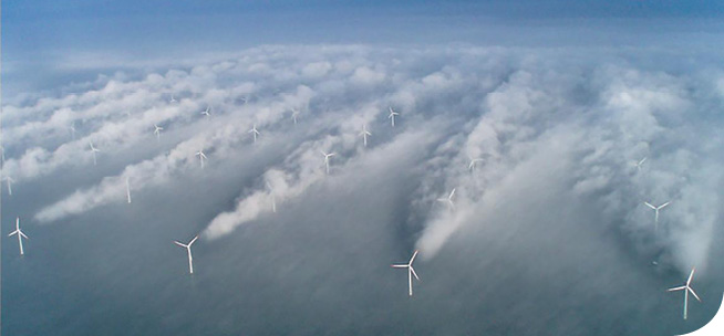
The classic photo of Horns Rev shows that wake swirl can extend far downstream.
Wind turbines see a broad range of dynamic loads that most large, ground-based rotating machines do not. They experience variation from the grid and generators (in the form of curtailments, grid loss, and voltage changes) and also see frequent wind changes that are occasionally extreme. Storms, gusty conditions, and even a sudden wind loss can cause significant variability in drivetrain loads and a reduction in the expected life of drivetrain components.
 Wind turbines see other challenging wind conditions as well. Extreme wind events have been defined for a long time. However, their ability to cause torque reversals of a magnitude that can damage a turbine has only recently been recognized and measured. The ultimate wind-load cases during normal running were defined during the 1990s in IEC 61400-1, Second Edition1, issued in 1999. This standard defined several transient wind events which turbine designers must address. Such events include:
- Extreme operating gusts: A decrease in speed, followed by a steep rise, a steep drop, and a rise back to the original level. The gust amplitude and duration vary with the return period.
- Extreme direction change (EDC): A sustained change in wind direction. The amplitude and duration of the change depend on the return period.
- Extreme coherent gust (ECG): A sustained change in wind speed, follows a cosine-shaped curve with the amplitude and duration depending on the return period.
- Extreme coherent gust with direction change: Simultaneous speed and direction transients similar to EDC and ECG.
- Extreme wind shear: a transient variation in the horizontal and vertical wind gradient across the rotor. The gradient increases and then falls back to the initial level, following a cosine-shaped curve.1
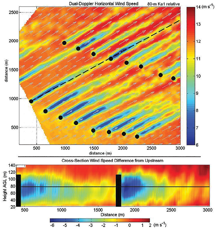
(Above) The color coded wind speeds for a wind farm were generated by a dual Doppler short wave radar developed by Texas Tech University. When the wind is such, wakes from turbines upstream blow to turbines downstream creating turbulence and load variations in their drivetrains. (Below) A side view of one row in the wind farm shows variation in wind speed with altitude.
When the standard was written, torsional reversals were not well known. In fact, torsional reversals are still not defined in standards and have also not been incorporated in gearbox standards. However, maximum structural loads caused by transient events are readily calculated and should be incorporated into design processes for various turbine systems. The Transient Torque Reversals (TTRs) imparted in drive systems have only recently been identified and recognized as a prime cause of increased O&M costs.
More problems with wind
The industry continually increases its understanding of the role that sheer winds and turbulence play in wind-power generation. Shear winds are a condition mainly caused by the topography of the surrounding countryside, locations near mountain ridges, or the nearness of buildings, highway overpasses, and other landmarks. A shear wind causes this portion of incoming wind to flow vertically up the turbines face, in addition to the normal wind going through the blade sweep. The blades can be loaded non-linearly, sending varying loads going through the drivetrain. Shear winds are most often experienced by turbines on ridge tops and those located near the front edge of a plateau. Winds striking the face of these mountains deflect vertically, resulting in shearing winds.
Other features in the surrounding topography cause turbulent winds. These are non-linear winds, those flowing without a pattern. Such wind causes the continual variation in the incoming loads to the drivetrain. The contours of the land, obstacles, and even thermal variations can cause the wind to slow down or accelerate. The area around a wind farm is rarely a homogenous plain.2 The more smooth or rough the terrain, the more the wind will be slowed or accelerated. Even the seasons cause a greater or lesser increase in roughness and turbulence, as crops and other features change, and high winds can magnify the problem. All these effects lead to varying loads on the rotating turbine blades. This means the aerodynamic and structural design must cope with conditions that are rarely optimal.3
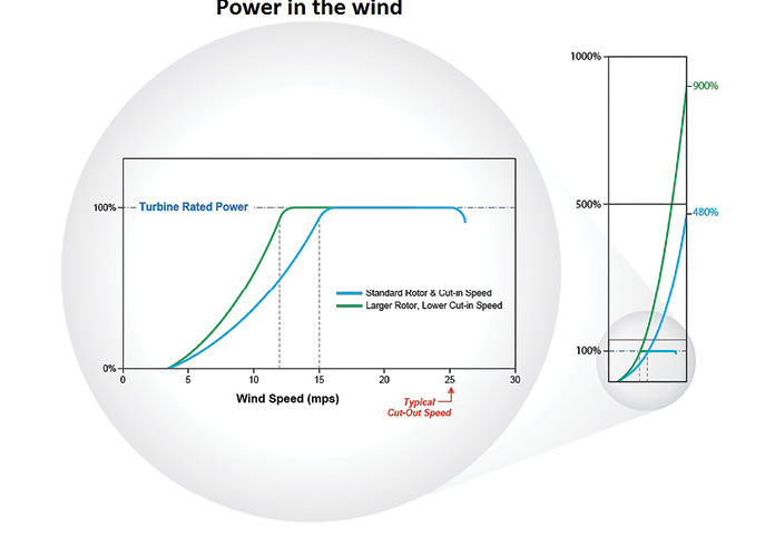
The blue upslope plot to the right is from a turbine with an original rotor. The blue plot to the left is from the same turbine with extended blades. The graph to the right shows a lot of untapped power in the wind.
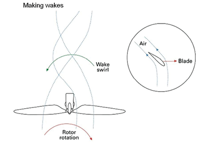
Swirling wakes
Even when there is no topographically related turbulence, wind farms create their own. Turbines cannot be placed too close together because downwind turbines see a “wake effect” from the leading turbines in a field. This can cause a reduction in extractable energy, as well as a significant increase in fatigue loading in the downstream machines.2 Some farms have even chosen to shut down various turbines in certain conditions to prevent this effect from damaging the machines.
The illustration, Making wakes swirl, shows the nature of wake effect downstream from a wind turbine. Obviously, a turning rotor produces the wake. Less obvious is that as lift forces on the blades generate torque, they have an equal but opposite effect on the wind, tending to push it around tangentially in the opposite direction. The result is that the air downwind of the turbine has “swirl” – it spins in the opposite direction of the rotor. When this turbulence strikes the blades of the next turbine downstream, it creates variable loading in the drivetrain. Occasionally, the wake swirl can align well enough with the downwind turbine rotor to create a momentary torque reversal, especially during high winds or emergency stops. The offshore Horns Rev wind farm produced the well-known industry photo showing the degree of wake effect that can occur. The photo shows the leading-edge turbines causing significant turbulence to downwind turbines, with impacts reaching far down the line of turbines when the wind is coming from a less than optimal direction.
 More recent research by Texas Tech University, Sandia, and NREL have helped advance the industry in designing the layout of wind farms. However, existing farms risk turbulence during normal operations, and in extreme transient events. Recent Dual-Doppler systems can finally measure the level of turbulence caused by nearby turbines. Wakes from one row to the next shows a best-case scenario, with significant distance between turbines in a non-optimized farm. Should the wind direction shift to a more perpendicular angle, the wake effect would be greatly magnified.
Why worry about torque reversals
The magnitude of dynamic torsional loading in wind turbine drivetrains during extreme transient wind conditions has not been well understood. This is especially true with respect to the cause of torque reversals. A wind turbine has two large inertial masses, one at each end of the drivetrain and rotating in sync. Blades typically share 80 to 90% of the relative inertia while the generator rotor has most of the remaining 10 to 20%. A torsional reversal is a rapid torsional unloading of the drivetrain and reloading in the opposite direction. This creates a prominent oscillation in the drive system affecting the gearbox bearings and gearing. While the rotation direction of the shafts do not change, the direction of the bearing load zone in the gearbox rapidly shifts up to 180°. Once this shifting begins, the system can wind-up back and forth many times causing multiple load-zone shifts until the oscillations dissipate. Current research has shown that the rapid reversals can cause significant impact loads on bearing rollers and races. It is believed that a significant number of gearbox failures are caused by the impact loads from these reversals, evidenced by the axial cracking observed in turbine gearbox bearing races. Torque reversals can occur any time there is a significant transient event, such as significant turbulence, shear winds, e-stops, curtailments, and on either end of the system
How extreme winds cause torque reversals
Modern wind turbines pitch their blades to moderate the power delivered to the generator and provide primary braking to safely decelerate the turbine. Depending on the blade-pitch angle, the blades can be either driving the generator or decelerating it. For
wind speeds from cut-in to rated turbine power, the blades are pitched to extract the maximum power possible. At higher wind speeds, the blades are pitched to safely deflect excess wind power by techniques called “pitching to feather” or “pitching to stall”. Pitching beyond an optimum feathering or stalling angle will cause the blades to decelerate the generator and can reverse the torque in the system.8,9 During an emergency stop at wind speeds close to cut-out, rapid blade pitching can reverse the torque in the system in less than one second. Even sudden changes in the blade’s angle of attack can cause a torque reversal whether it is towards feathering or stalling.
This is precisely the issue with extreme wind shear, and gusty and turbulent winds. A sudden change in direction can result in momentary torque reversals that can cause damage to the turbine drive system. Blade-control systems cannot always react fast enough to mitigate these fractional-second loads, especially during rapid stops during high wind speeds.
Wind-over-power ratio
The maximum accessible wind power the blades must withstand compared to the rated power the turbine could be termed the Wind-Over-Power Ratio (WOPR). The ratio can help understand the challenges a turbine has in surviving torque reversals without damage during extreme high winds.
For wind speeds from cut-in to rated power, turbine controls strive to extract every bit of accessible wind power they can. So the accessible wind power and the extracted wind power are essentially the same. At speeds above the rated turbine power, blades are pitched in an effort to safely deflect excess power in the wind. The WOPR number is based on the extracted and deflected accessible wind power just before cut-out speed.
Wind power increases as a cube function of wind speed. That means, doubling the wind speed provides an 8 fold increase in wind power (23 = 2x2x2 = 8). This provides an easy way to calculate the WOPR. Like so:
Rwop = (Vcut out / V rated power)3
Where Rwop = wind-over-power ratio, Vcut out = cut-out speed, and V rated power = lowest speed that produces the turbine’s rated power. For typical turbines with cut-out speed of 25 m/s and rated power wind speed of 15 m/s, the WOPR is
Rwop = (25 m/s / 15 m/s)3
= 1.6673
= 4.6.
This means that as the wind speed approaches cut-out, the blades could theoretically overpower the drive system by a factor of 4.6, if the generator was large enough. For turbines with longer blades that achieve rated power at 12 m/s and cut out at 25 m/s, the WOPR is 9. That means that if the generator was large enough, the blades could put nine times the power through the drive system. Of course, turbine designers do not allow this. But the generator does have a significant inertial mass that can momentarily resist transient wind loads on the blades and cause brief torque-reversal spikes through the drive train. This is especially true at high wind speeds and during stopping protocols when the blades pitch rapidly, such as in high wind shutdowns, high vibration, or grid loss.
Obviously, there is a risk in operating wind turbines with high WOPR numbers. High wind gusts have far more power to cause damaging torque reversals. Some turbine manufacturers recognize this risk and have reduced the cut-out speed when using longer blades. One turbine manufacturer, for example, has reduced the cut-out speed from 25 to 20 m/s for their 100 and 110-m rotors. This can negatively impact the annual energy production.
 Turbulent conditions and their load effects –field data
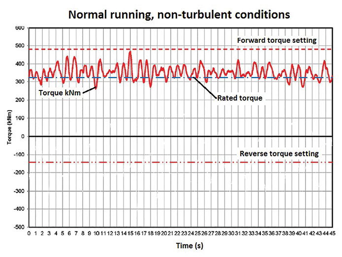
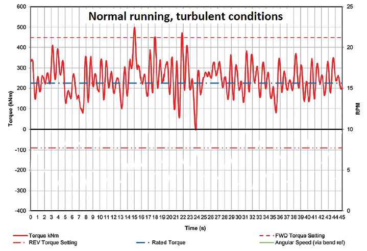
In standard wind conditions, a normal running turbine experiences small normal torque variations, such as in Normal running non-turbulent conditions. A torque sensor can detect small changes in load during normal operation. Torque variations are minimal and linked to slight wind changes, control system operations, and other similar events. This is readily handled by the control system and power converter, allowing for proper power output from a turbine. However, steady state wind flow is abnormal. Torque traces in a more dynamic wind is likely to show several conditions. For example:
- Torque oscillations can be significantly higher. Normal running, turbulent conditions (pg 56) shows that a non-stopping event can still cause a torque load 200% of nominal torque. The turbine that generated the trace is in a desert, subject to turbulence caused by mountains and other nearby turbines. The plot shows significant load variations. This variable loading sets the stage for the drivetrain to wind and unwind, thus amplifying the effect of a torsional reversal.
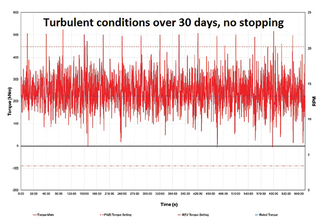
- Aggregate data. When reviewed in aggregate, the data is even more concerning. In standard operation (no stopping events) over a 30 day span, the illustration Turbulent conditions over 30 days shows positive torque variations from 250% of nominal and those dropping to negative torque values. Swirling winds and turbulence are causing these significant drivetrain torque variances which also produce potential damage to bearings and gears.
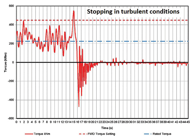
During an event, the plot in Stopping in turbulent conditions, shows what happens when a fault occurs in the same turbine that produced the previous plots. Large variations in torque appear on the left of the plot (similar to the above plots) but still only in the forward direction – no reversals. (Forward loading refers to standard running torque, positively loading the bearings in one direction.) The fault then generates a large forward spike, followed by repeated torsional reversals. These are not worst-case events, and potentially can be increased in magnitude at higher wind speeds.
Increased torque from blade extensions
To improve power production, the industry is trending toward increased blade lengths. The idea is to decrease the cut-in and rated-power wind speeds for greater energy production in low and medium-speed winds. A length increase of only 15 ft. per blade can generate 7% more power per year, according to one turbine manufacturer.10 This provides a significant economic improvement at lower wind sites. The green trace in Power in the wind shows the decrease in cut-in speed, speed for rated power, and increase in power potential.
 Unfortunately, there is also a downside to the increased blade-sweep area. As wind speed increases beyond rated power, more potential energy in the wind will be deflected by pitching the blades. Even with precise pitching, the risk of torque reversals caused by wind gusts will significantly increase as winds approach cut-out speed.
An advantage of an existing farm is that it can provide accurate historical data which allows for a better financial analysis of new ideas, such as blade extensions. Unfortunately, while blades and control systems are changed to allow for more wind capture, other components, such as the gearbox and couplings, often go unchanged. With slim safety factors in modern turbine gearboxes, the true costs of the change in blade length may not be known for a few years of operation. The damaging effects of transient loads, now enhanced by the increase in WOPR, may shorten the gearbox life unless measures are taken to control the damaging effects of torque reversals.
An asymmetric approach to torque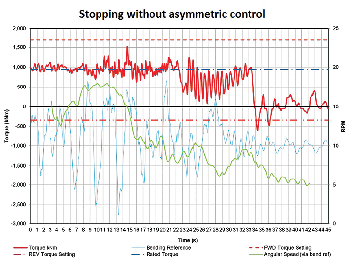
A standard torque limiter has to be set for extreme high forward torques and treats reversals with the same torque setting. This means it likely will provide little or no protection against torsional reversal. With the variability inherent in the wind, the best approach would be to take an asymmetrical approach to torque control.
Asymmetric torsional control (ATC) simply means having different torsional setting to limit forward and reverse loads. In the normal forward drive mode, an ATC provides exactly the same power production and torsional profile for which the turbine was designed and certified. It is only during a transient torque reversal that it protects the turbine from rapid high magnitude torque reversal load spikes.
It works like this: When a torque reversal exceeds the reverse setting of the ATC, it frictionally slips just enough to control the magnitude of the reversal and slows the rate at which the reverse load can impact and damage the drive system. An ATC can dampen these transient loads to a predetermined level. Reversed loading is reduced to a significantly lower level, thereby protecting bearing rollers and races when they are at highest risk.
With an ATC, the reverse frictional slip setting can be set as low as 40 to 50% of the rated turbine torque. Reversals as high as 200% of rated torque have been recorded on some turbines. A turbine with an ATC and a reverse slip setting of 40% of rated turbine torque, the magnitude of the reverse impact loads in the drive system would be reduced by 80%. In addition, the frictional slippage slows the rate of load increase, thus further reducing what would be an impact that can shorten the fatigue life on gears, bearings, and every other component in the drive system.
Controls can only do so much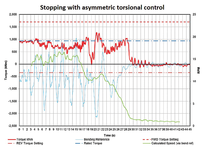
To maintain safe operations in low-wind optimized turbines, control system must maintain a higher level of control than their shorter-blade counterparts. Unfortunately, in shear winds and turbulent flow, these pitched long blades may actually catch significantly more wind than needed. With an increased surface area, it is difficult to adapt to transient wind conditions quickly enough to mitigate the potential damage. A control system should detect the event occurring and initiate the mechanical solution. Most control systems can react to data inputs captured over multiple seconds or minutes, but not the fractions of seconds needed to protect against a sudden transient reversal. Even with optimal control response time, the reaction of a mechanical system takes time. In addition, if the turbine reacts too quickly, it can increase the risk of reverse torsional events. Regardless of the control’s reaction, the additional energy and loading will have to be absorbed somewhere in the turbine’s drivetrain.
Stopping without asymmetric control presents a torque trace from a fairly basic stopping event in a common 1.6 MW turbine. This turbine has one of the most advanced controllers available and does a good job of preventing the massive horizontal “Christmas tree” torque spikes seen by many older turbines. Still, significant oscillations are present. Forward-loading oscillations have significant magnitude that could lead to fatigue in drive components. The torque reversal at the end is an impact load on suddenly loaded and likely misaligned bearing rollers, potentially a root cause of white etch damage.
 Stopping with an asymmetric torsional control shows the trace from such a system. Damaging loads are reduced to a more manageable level. The magnitude and the frequency of the shock load has been reduced and the reversals are almost completely eliminated.
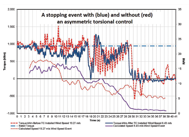
Overlaying the last two plots in Stopping with and without an ATC shows that even with advanced controllers, an asymmetric mechanical torque control is still a major improvement in reducing drivetrain loads. Standard torque limiters cannot achieve this reduction. In these overlayed field plots, the first shows how ineffective the standard limiter was at damping these loads, and for a relatively minor stopping mode. These loads would be significantly greater in a full e-stop or other less frequent but still likely event in a year of operation.
The solution to torque reversals must be a one that approaches torque loads asymmetrically, as seen in the further field data in the overlay plot. AeroTorque has spent years gathering this real-world data from turbines in the field. Our WindTM monitoring gear has been on seven different turbine models, turbines from a broad spectrum of manufacturers and ages. All of the turbines we have monitored have shown uncontrolled transient loads and the need for an asymmetric approach.
How torsional reversals can cause axial cracks in bearings
- Axial cracking in wind turbine gearbox bearings start with microscopic sub-surface material damage in the bearing inner ring, seen through a microscope as a white etched area (WEA).
- The WEA damage is actually tiny super-hard slivers that act as inclusions in ultra-clean bearing steel. They are created underneath the inner ring surface so that normal rolling action fatigue loading will cause cracks to propagate to the surface and form axial cracks. They are believed to be caused by some combination of impact loading, surface traction, or severe and rapid plastic deformation, or all three.
- All these load conditions can happen simultaneously during a transient torque reversal in wind turbines. Many in the industry now believe torque reversals to be the likely primary cause of axial cracking.
- AeroTorque has recorded many torque-reversal events in many types and models of wind turbines. The worst recorded torque reversals on each turbine model appear to occur during some combination of emergency stops, high wind speeds, and gusty wind conditions.
- Older wind turbines with blade-tip braking tend to have frequent torque reversals that do not happen rapidly enough at a high enough magnitude to cause WEA damage. They do damage to bearings and gears in a more conventional way (see Windpower Engineering and Development magazine, September 2012).
- Newer megawatt and multi-megawatt turbines with blade-pitch control tend to have fewer torque reversals but their magnitude and rapidity can be much more severe. Axial cracking and WEA damage began to appear with turbines exceeding 1 MW. The larger the wind turbine, the greater the magnitude and rapidity of the torque reversals.
- It only takes one severe transient torque reversal event to create a subsurface super-hard WEA sliver in the bearing inner ring.
- Bearing inner rings typically can show multiple axial cracks, potentially indicating many torque reversal events. It only takes one WEA sliver to grow into an axial crack and fail the bearing.7
For further reading:
1. International Electrotechnical Commission. IEC 61400-1, Second Edition. 1999-2
2. Ragheb, M. “Wind Shear, Roughness Classes and Turbine Energy Production.” (2012): n. page. 6 Feb. 2012. Web.
3. Tzanos, John, Kostas Margellos, and John Lygeros. “Optimal Wind Turbine Placement via Randomized Optimization Techniques.” PSCC-central.org. Power Systems Computation Conference, 29 June 2011. Web. 1 Oct. 2014.
4. WE Handbook- 2- Aerodynamics. Wind Turbine Blade Aerodynamics (2009): 1-10. Gurit Wind Energy Handbook. Gurit Holding AG, 14 Dec. 2009. Web. 1 Oct. 2014.
5. Müller, Bernd. “Turning Many into One.” Pictures of the Future Siemens Corporation (11 May 2011): 97-98. Print.
6. Schroeder, John. Improving Wind Farm Efficiency Using Advanced Doppler Radar Technologies. Lubbock, TX: Texas Tech U, 2013. Print.
7. Herr, Doug, and Dave Heidenreich. Understanding the Root Causes of Axial Cracking in Wind Turbine Gearbox Bearings” Tech. 2013. Print.
8. Schubel, Peter J., and Richard J. Crossley. “Wind Turbine Blade Design.” Energies 5.12 (2012): 3425-449. Web. 3 Oct. 2014.
9. Maheswari, R. Uma, and J. Tamilvendhan. “Analysis of Modelling of Active Stall Controlled and Active Pitch Controlled Variable Speed Wind Turbines.” International Journal of Modern Engineering Research 2.4 (2): 2662-67. http://www.ijmer.com/papers/Vol2_Issue4/EE2426622667.pdf. IJMER, 27 July 2012. Web. 1 Oct. 2014.
10. Jaffe, Mark. “Vestas Unveils Longer Turbine Blade to Boost Power and Sales.” – The Denver Post. The Denver Post, n.d. Web. 30 May 2013

Filed Under: Featured, News, O&M, Turbines