Tristan Le / Performance Engineer / AES Corporation
Most turbines use mechanical anemometers and wind vanes to measure conditions at a wind farm. Data collected, including the wind speed and direction, is then sent to the turbine controllers, which help optimize the blades for maximum wind generation. However, there is often inherent vulnerability within these existing OEM monitoring and control systems, which can lead to higher maintenance costs and poorer turbine power performance.

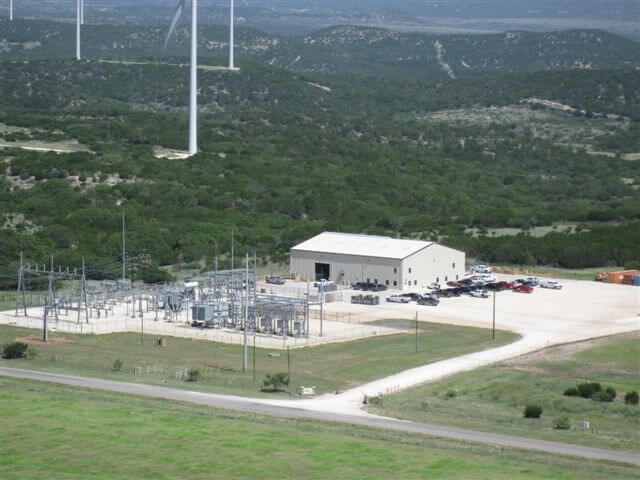
AES Corporation maintains 296 wind turbines at its Buffalo Gap Wind Farm.
One problem is that the sensors use moving parts. The anemometer uses “cups” for wind speed measurements and the wind vane uses a “vane tail” for measuring vector change, or wind direction.
The physical inspection of a large population of such turbine sensors at a Texas wind farm revealed the majority of failures were linked to bearing problems that led to accuracy degradation and shortened instrument life. Increased bearing rolling resistance also affected wind measurement accuracy, and therefore turbine efficiency, because this data is used to optimize turbine performance.
Winter did not help this wind farm either. Cold weather had a negative impact on turbine performance, freezing the exposed mechanical components of the sensors and causing another maintenance issue.
The wind farm
The 296 turbines at AES Corporation’s Buffalo Gap Wind Farm in central Texas were constructed in three phases from 2006 through 2008.
The break down: phase one comprises of 67 Vestas V80 1.8-MW turbines, phase two has 155 GE 1.5-MW turbines, and phase three totals 74 Siemens 2.3-MW turbines. The capacity of the wind farm is 524 MW, currently making it the seventh largest wind farm in the world. It annually generates more than 1,600,000 MWhr (1.6TWhr) of clean, renewable energy.
Although quality wind turbines were installed from leading suppliers, these units were not immune to sensor issues. For example, the Siemens turbine suffered the greatest impact during freezing weather. Only a slight amount of moisture coupled with freezing temperatures would cause the anemometer and wind vane to lock up, effectively shutting the BG3 turbines down.
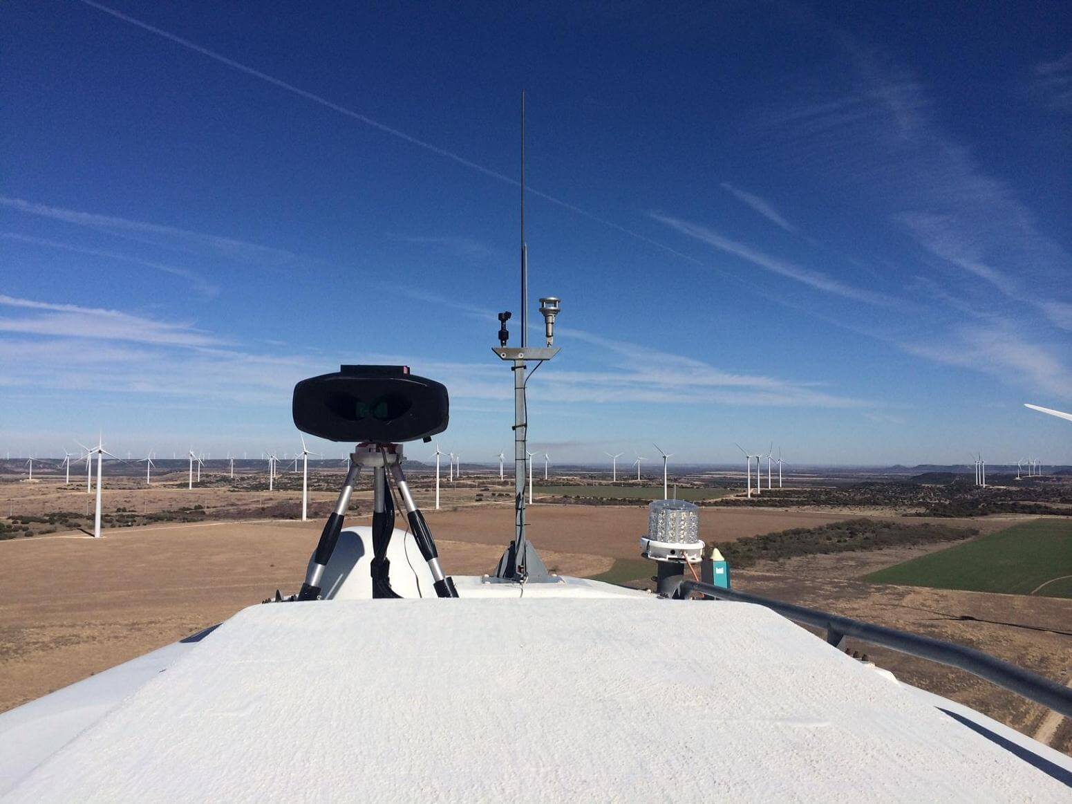
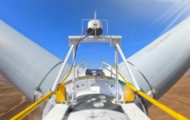
The ultrasonic wind sensor on a GE turbine is visible on the middle mast to the right of the tall antenna. The tripod-mounted device to the left of the nacelle roof is a Wind Iris LIDAR unit that assists in calibrations.
The heated GE sensors were slightly more tolerable to winter weather, but experienced a much lower mean time between bearing failures because of the higher operating temperatures of the sensor bearings.
Another problem was sensor performance. Research and testing proved that the cup and vane type sensors were not accurate in high turbulence or under steep wind shear conditions. The devices were also not suited for use downwind of the rotor because of the strong rotor wash or air turbulence at the site.
A reason for failure
Rotor acceleration increases gradually with wind speed during normal operation. However, when the anemometer under-reports wind speed from a partial failure, there is an increase in rotor acceleration indicating that a large amount of wind energy (typically around 10%) is not being converted into electrical energy. Instead, that energy is absorbed through the main bearing and drivetrain, and dissipated by the rotor motion.
The rolling resistance in anemometer bearings typically increases over time until they seize completely. Ideally, when a turbine recognizes abnormal loading from increased rolling resistance, it will fault before a complete seizure. But in many instances, a turbine never recognizes the problem. This partial failure of an anemometer is more destructive than a complete failure because it can destroy a turbine’s drivetrain.
To operate safely and efficiently, wind turbines need accurate information on wind conditions. Protecting a turbine makes it vital to record wind data, especially during turbulence. Accurate measurements are not possible when an anemometer’s rotational speed is unable to change at a fast rate, as is the case when operating with faulty bearings.
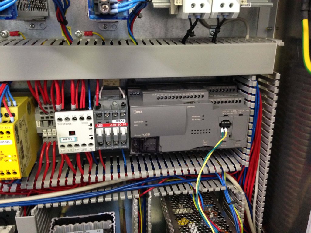
The new IDEC PLC with power supply and the existing turbine controller, all fit into a wind turbine’s nacelle.
The turbine control system adjusts blade pitch and rotor speed differently depending on the degree of turbulence. It does so to protect the blades and drivetrain from fatigue related to poor use of the blade airfoil. Poor or inaccurate anemometer measurements mean incorrect adjustments and increased fatigue.
The need for precise measurement of wind direction is also important. At the Buffalo Gap Wind Farm power output significantly decreased once the turbines exceeded ± 10 degrees of yaw misalignment.
Improving the system
Research into the anemometers and wind vanes on the Buffalo Gap wind turbines led engineers to use ultrasonic instrumentation or high-frequency sound energy to conduct examinations and make measurements. Ultrasonic instrumentation was determined to be a measurement tool that could potentially provide more accurate and reliable indication of wind conditions.
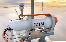
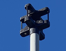
Based on this assessment, engineers replaced the wind measurement mechanical sensors with a single ultrasonic sensor (see image, An ultrasonic sensor) and used an IDEC programmable logic controller (PLC) to convert signals from the sensors and gain better control the wind turbines. IDEC is a manufacturer of control, operator interface, and other automation components. The company’s controller proved reliable, user-friendly, and affordable, which was imperative for a site that needed to install a total of 296 of these components.
The intent was to convert the signal from the ultrasonic sensor into a usable form for the turbine controllers. Available ultrasonic sensors were unable to provide the specific and varying information required for the different turbine controller types. Therefore, an IDEC FT1A-PC3 Modbus adapter was installed, which accepts the input from the ultrasonic sensor signal and sends it to an IDEC FT1A-H40RSA PLC via Modbus.
Data from the IDEC PLCs is transmitted to AES Corporation’s control center for analysis.
The PLC acts as an emulator for the turbines because the research engineers were able to write specific ladder programs based on the make and model of each turbine. This let the PLC emulate the digital-logic-sensor signal required by each turbine’s controller.
The engineers were also able to create algorithms to provide non-linear corrections to dynamics, such as the nacelle transfer function and yaw bias. All the IDEC equipment and a 240W power supply fit into a turbine’s nacelle, along with the existing OEM turbine controller.
Using LIDAR, a light detection and ranging technology, to validate anticipated performance and the continued application of statistical tools and methods, the team realized it could further improve turbine performance. Yaw bias (alignment) and wind speed correction (nacelle transfer function) were discovered to be inherently dynamic and non-linear. Using this data, engineers were able to write algorithms to correct the distorted wind speed and direction data before interpretation by the turbine control system — thereby increasing energy capture and reducing drivetrain fatigue.
Data from the PLCs is transmitted to a control center where engineers perform statistical analysis, program the PLCs and turbine controllers, and analyze data to predict failures before they happen.
Filed Under: News, Sensors