Mauricio Esguerra, Consultant, and Hubert Kreis, Owner and CEO, ed-k, www.ed-k.de
Three-phase reactors are indispensable components for wind power systems. They are used in line filters to reduce harmonics of the pulse frequency, they prevent resonances, and achieve compliance with grid codes and EMC regulations. On the generator side, inductors are used in dv/dt filters and chokes to limit voltage peaks and reduce bearing currents. The challenge to cost-effectively design wind-energy inductors depends on the ability to optimize system components in terms of size and weight. To that end a precise, reliable and portable inductance test at high current is a basic prerequisite for both component manufacturers and wind-power system engineers.
Conventional inductance testing
Three-phase inductors are normally built by winding three-legged laminated cores with constant cross-section areas. The main parameter is the ac impedance at the rated current which is calculated from the inductance L as follows:
XL = 2 π fL (1)
Where XL = ac impedance, ohms; and f = frequency, 50 or 60 Hz.
The inductance of each leg of the reactor is measured by connecting the inductor to a variable high current, 3-phase sinusoidal 50 or 60 Hz supply. The current I for all three coils is adjusted individually to within the rated rms current range. The rms voltage across each coil can then be read. The amplitude inductance of each phase k is given by:
Lk = Vk / (2 π f Ik) (2)
Where Lk = inductance, henry at phase k ; Vk = voltage, volts at phase k and Ik = current, amps at phase k; and k = phase, 1, 2, or 3
The test setup requires three voltage and three current meters and is normally used only to test the inductance at a single current value. The difference between outer and middle coils (about 4 to 9%) is mostly neglected.
di/dt or Pulse inductance test
This test method is widely used for testing single phase power chokes at high currents. It applies a rectangular voltage pulse to the component being tested. A current ramp is then created in the test component and its di/dt slew rate used to calculate a complete differential inductance curve up to saturation, as follows:
L(I) = [V(I) – RL • I] dt/di (3)
Where I=current, amps; L(I) = inductance as a function of current, henry; V(I) =voltage as a function of current, volts; and RL =DC winding resistance, ohms.
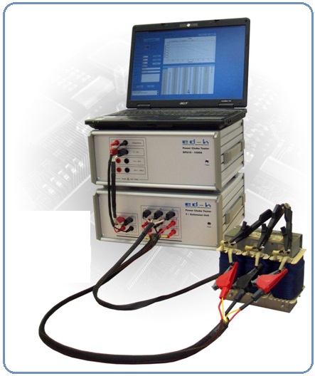
A compact and highly precise test instrument, DPG10 by ed-k (www.powerchoketester.comed-k.com), allows currents up to 1,500A for single phase testing. It has been available in the market since 2005 and is widely adopted as the industry standard for applications such as solar and UPS inverters, commutation equipment, PFCs, storage, and line chokes for SMPS; and rotor and stator inductance. Thanks to its high current capability this testing method has complemented and even replaced conventional LCR sine wave bridge methods in these applications.
Due to the advantages of this testing device, manufacturers and users have often requested to implement this method for three-phase testing. It is possible to use the single-phase device for three-phase inductor testing when a number of points are taken in consideration:
- Use the already implemented amplitude inductance function of the instrument
- Connect the inductor coils in a skillful manner to obtain a magnetic flux distribution within the inductor as close as possible to the three-phase excitation used in the conventional inductance test
- Calculate the equivalent inductance for the outer and middle coils
- Correct the current axis for the equivalent rms current of the conventional inductance test
- Correct for the frequency effects coming from the excitation with a rectangular pulse to show the equivalent value for 50 or 60 Hz sinusoidal excitation
Implementation and results
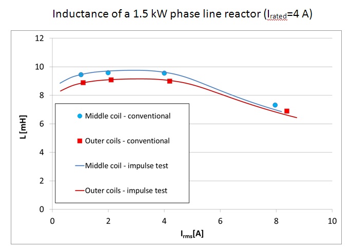
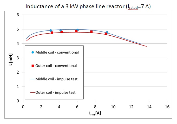
To allow for automatic and reliable operation, the company has developed a three phase extension unit and corresponding software to consider the effects mentioned above. It yields an excellent correlation to conventional testing of inductors of different sizes and power ratings ( Fig. 1 to 3: phase line reactors for motor drives with rated power 1.5, 3.0, and 15 kW).
Notice that a test lasting only a few seconds yields a complete inductance versus current characteristic. The same test using the conventional method mentioned above (usually with manual current adjustment) would take a substantially larger amount of time.
The basis of the software used to determine the equivalent inductance is based on a careful analysis of different factors:
- Analytical three phase magnetic circuit calculations
- Finite element magnetic field simulations (Fig. 4)
- Core material characteristics: permeability vs. flux density and permeability vs. frequency
- Magnetic response to a rectangular pulse
- Air gap effect on the magnetic circuit
 It is important to note that the material and air gap of the device under test are unknown. The corresponding information needed by the calculation algorithm is derived directly from the tested inductance vs. current curves.
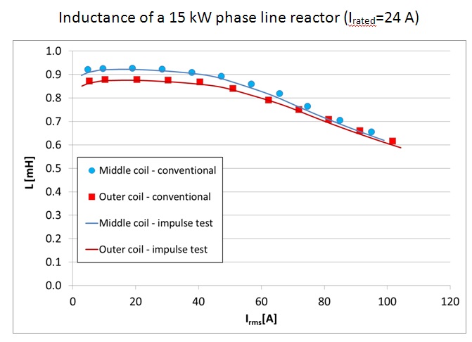
Figure 1 top, Figure 2 middle, Figure 3 bottom
As shown in Fig. 5, (below) the test system is capable of testing at high maximum rms current values in dependence of the inductance value of the device under test.
Almost any inductor can be tested with enough margins to the inductance vs. current limit including even large inductors up to a rated rms current of 1 kA. An instrument capable of testing at rms currents up to 2 kA is currently under development and a new instrument generation capable to testing up to 6.5 kA has been devised. These will allow covering the full range of wind energy reactors up to the highest power ratings.
The pulse testing method has another key advantage with respect to current waveform distortion due to magnetic saturation. As shown in Figs. 1 to 3 the inductance tested with the conventional method at high currents tend to be higher. This is a systematic error coming from a distorted current waveform with a high crest factor (Fig. 6): its equivalent sinusoidal (rms) waveform has a lower current value and according to Eq. (2) yields an apparently higher inductance. There are no testing artifacts at any current value for the pulse-test method due to a non-sinusoidal current signal. For this reason the inductance tested with this method at overload currents is as accurate a value as at rated current.
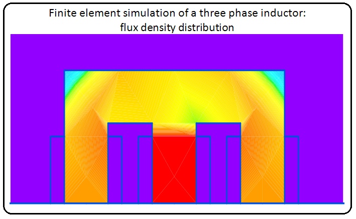
Figure 4 FEA of 3 phase inductor.
Conclusion
The new 3-phase testing system based on the proven DPG10 technology can rationalize factory and in-situ inductance testing. By virtue of the complete inductance curves it is also an efficient and highly precise engineering tool to develop and select optimized components for various applications. This is especially the case if the inductance must be considered at overload currents.
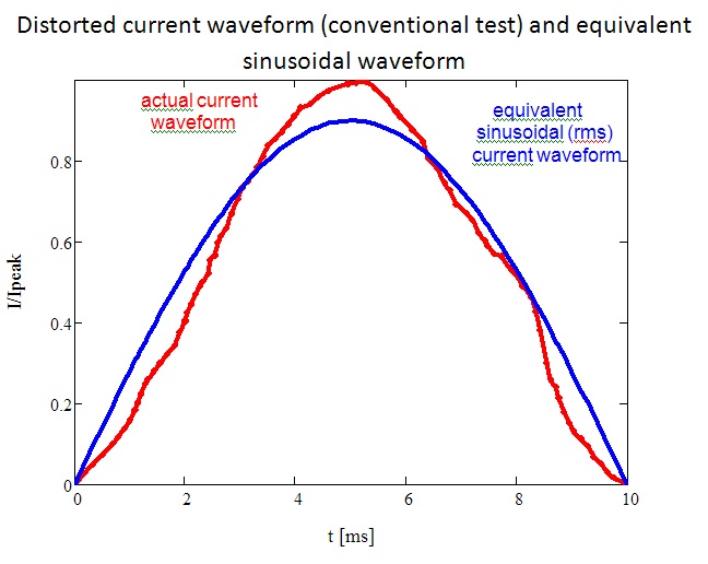
Figure 6
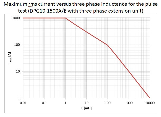
Figure 5
Author biographies
Mauricio Esguerra is Independent Consultant for Magnetics & LED Lighting in Taufkirchen (Munich) and can be reached at mauro.esguerra@gmail.com
Hubert Kreis is Owner and CEO of ed-k in Planegg (Munich)and can be reached at h.kreis@ed-k.de
Filed Under: News, O&M


Dear sir ,
Please send me the exact turns formula for line and load reactors calculation I’m designing my own reactors for motor and vfd protection for my final year projects. Looking for your reply .
Regards
Vibin
Dear,
I am PhD student, part of my doctoral research is for understanding the construction of three phase input line inductors as input for adjustable speed drive 10KVA whith rated current 14 A and 500 V.
Please, could you help me by sending the latest work has been done for designing three phase input line inductore to reduce the size along with high efficiency.
Tel no. 07448348965
I look forward to hearing from you
Kindest regards
Mohamed