Rukiye Canturk, University of Massachusetts Lowell
Murat Inalpolat, University of Massachusetts Lowell, Murat_Inalpolat@uml.edu
Abstract from the Proceedings of the 2015 COMSOL Conference
Modern wind turbine blades consist of composite airfoil shaped structures that form a hollow acoustic cavity. Because of continually varying aerodynamic forces, gravitational loads, lightning strikes, and weather conditions, all blades will experience leading and trailing edge splits, cracks, or holes. When acoustic sources (wind flow) excite this dynamic cavity structure, blade damage will manifest itself in changes to the cavity acoustic response. One of the most robust tools for modeling acoustic phenomena in real structures is finite element analysis. The multi-physics modeling capability of COMSOL lets us model complex structures and acoustic wave propagation through blade surface with damage and help improve the nondestructive inspection technology as proposed in this study.
Introduction
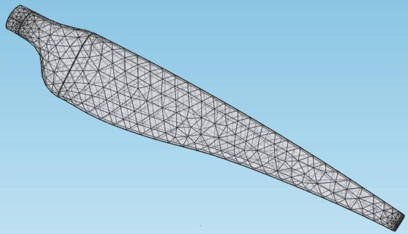
This finite element mesh was used for the subscale wind turbine blade model.
Clean energy generation, supply, and storage demands have been continuously increasing around the world. This proven technology is on the rise and currently at a 66 Gigawatt overall capacity only in US and a lot more in Europe [1]. However, reliability problems and the cost of operability and maintenance (O&M) are the common factors impeding the value and net gain generated by wind turbines. Their blades are arguably the most critical components because they capture the energy from wind.

These terms describe the blade.
Blades are in direct interaction with wind as well as other environmental factors, such as temperature variations, humidity, erosion, and more. Because of the continually-varying aerodynamic forces, gravitational loads, lightning strikes, and weather conditions, all blades will experience leading and trailing edge splits, debondings, cracks, or holes. To detect and identify the blade faults such as holes, cracks, and delamination, several methods and approaches have been developed and are currently being used in the inspection and maintenance areas.
Vibration-based, acoustic emission and wave propagation techniques are in common use for evaluating the structural integrity of wind turbine blades [2-4]. Photogrammetry-based optical techniques have recently been used to detect defects from the wind turbine blades [5-11].
Ultrasound-based inspection is one of the most widely used blade inspection techniques in industry and has been successful demonstrated in the literature [12-15].
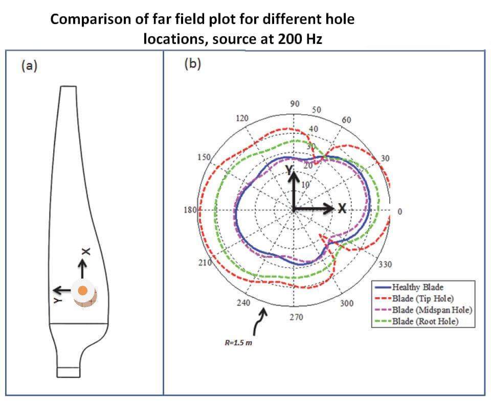
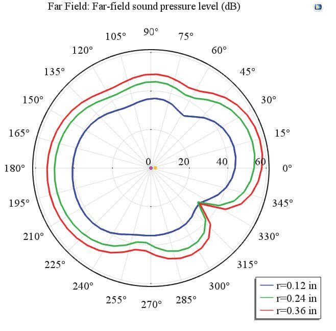
The comparison of far-field plot for different location of hole (d=0.12 in), source at 200 Hz.
Acoustic beam forming is an excellent but costly technique that has been demonstrated to succeed under certain conditions [16-20]. Acoustic signature taken from the structure, before and after the defect, will let us differentiate the fault existence and can also be used as a blade inspection method. Aizawa et al. [13] investigated damage detection of wind turbine blades by installing an audio speaker inside of a wind-turbine blade and qualitatively characterized the sound radiation using a microphone array. Their observation in the end was that the faults would change the radiated sound energy from the object. One other potentially viable damage detection method, vibroacoustic modal analysis, could also be used for damage detection. Arora et al. [2] showed that vibroacoustically-coupled mode shapes would change due to damage on the structure by exciting the structure using a loudspeaker from inside a box. Other studies that utilize vibroacoustic modal analysis for damage detection from composite structures are rather sparse and only limited to a few papers [21-24].
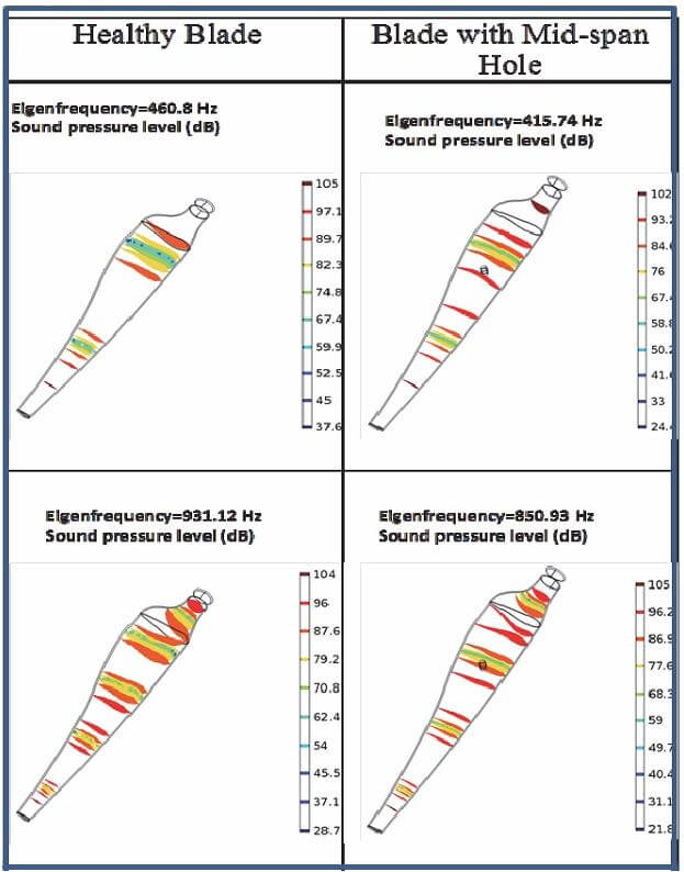
The comparison of blade acoustic mode shapes (healthy blade and blade with mid-span hole).
In this paper, a blade-inspection method that relies on determination of the changes to the acoustic mode shapes and perturbations to the perceived source directivity of wind turbine blades is proposed. COMSOL multi-physics was used for all the subsequent analysis required for the initial development of this new methodology. The subsequent analysis include a “healthy” blade with no defects or damage, and a “damaged blade” with an intentionally created opening (circular hole) with varying location and size. An acoustic-solid interaction model was developed to investigate the sensitivity of acoustic modal properties (eigenvalues and eigenvectors) to the changes on the severity (size) and location of the damage on the wind turbine blade.
The comparison of far-field plot for different location of hole (d=0.12 in), source at 200 Hz.
Formulating the problem
The finite element analysis of composite blades with damage requires a multi-domain modeling approach. The blade is treated as a solid body made up of a composite material with averaged material properties of density at 1064 kg/m^3 and modulus of elasticity at 4.85 GPa [25]. The internal cavity of this subscale blade is modeled as air and the damage is modeled as a separate air domain coupled with the internal and external air regions. This turns the overall problem into a fluid-structure problem and to solve the fluid- structure problem, acoustic-solid interaction interface within COMSOL Multi-physics was utilized. Specifically, the following parameters for both healthy and damaged blade were obtained to create a basis for the continuation to pursue this new technique:
- Acoustic natural frequencies
- Acoustic mode shapes
- Acoustic directivity (SPL at the far field ~1.5m away from the source).
The solid model required for the FE analysis of the subscale wind turbine blade was created in SolidWorks and imported into COMSOL. The subscale model illustrates the nomenclature used in this paper on the simplified blade geometry.
Tetrahedral elements were used in modeling the structure in COMSOL. The minimum element size was selected as 0.03 m for the healthy blade and reduced when the damage was introduced.
 Computational acoustic modal analysis of the blade
The acoustic modal properties of the turbine blades can potentially be used for damage detection and thus employed in this study. Natural frequencies and acoustic modes of the blade were determined by using the acoustic-solid interaction modules. This is useful to optimize the virtual sound source (emulating a real acoustic speaker) location and detect the damage from blades. On the other hand, because of the complex geometry of the internal cavity of the wind turbine blades, it is generally not straightforward to predict the optimal sound source location that would efficiently excite the internal cavity of the blade.
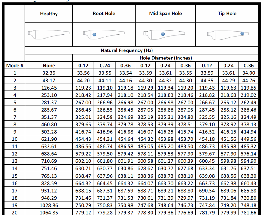
 The computational acoustic interrogation presented in this study is a means to identify the mode shapes and the corresponding acoustic pressure distributions which can be leveraged to find out the best sound source as well as receiver (microphone) positions. First, the natural frequencies (eigenvalues) of the blade cavity were obtained for a healthy baseline case. Then, the computational runs were repeated for the same blade geometry when the blade has either a tip hole, a midspan hole, or a root hole to see the influence of damage and its location on the natural frequency variations. Moreover, the size of the holes located at different blade positions were varied for understanding the sensitivity of the modal properties of the blade to the severity of the damage. These results are tabulated in the first table.
 Note that a certain natural frequency under the healthy case column may not be compared with the result in the row for the damaged blades because the mode shapes change and differ significantly. In other word, the frequencies seeming similar or close to the healthy case frequencies mostly belong to a different mode. Besides for the very first few modes, all the natural frequency values tend to decrease with the existence of the hole. The higher the natural frequency the higher the influence of damage on the frequency would be. Besides, the severity (size) of the hole has relatively less overall effect on the natural frequency values obtained.
Secondly, the acoustic mode shapes are obtained and illustrated through the iso-surface plots in order to indicate the identical pressure distribution regions inside the cavity. The magnitude (Sound Pressure Level – SPL in dB) of the pressure is illustrated using a color scheme in Table 2, where a spectrum ranging from dark blue to red facilitates a pressure value distribution from low to high. The mode shapes can be visualized more clearly if the iso-pressure surfaces can be virtually connected with a curve that goes through the high pressure points at the axial locations where there exists a red plane and low pressure points at the axial locations where there exists dark blue plane inside the blade cavity.
The two example frequencies, 460 and 931 Hz were selected to illustrate the mode shape changes due to the existence of damage. These two modes have a “high pressure point” where the damage was previously prescribed. The damage, if located at or close to the high pressure regions of the mode shapes, affect the mode shapes as well as natural frequencies comparatively more. This highlights the locations where the sound sources should be located at locations close to these high pressure points (anti-nodes) to excite the cavity more efficiently.
Far-field directivity
The other important goal of this computational study was to understand the influence of the damage on the far field sound pressure distribution. In this investigation, far field directivity plots were employed to clearly exhibit the difference between several different analysis at once. The results of this analysis are rather important to understand the best position of a measurement microphone to be located outside of the blade in the far field. A monopole with 0.01 m3/s source strength is located inside the blade to excite the acoustic cavity of the blade as schematically shown in Figure 3(a). A full integral far-field evaluation was performed approximately 1.5m from the source. The directivity plot in Figure 3(b) illustrates the directivity information for the healthy blade in comparison with the damaged blade with a 0.12-in. diameter hole located at various locations. The comparison presented in Figure 3(b) indicates that the microphone positions that are outside the blade, blade root direction could potentially make the best microphone position in a practical application as it receives the highest directivity and thus the radiates sound waves.
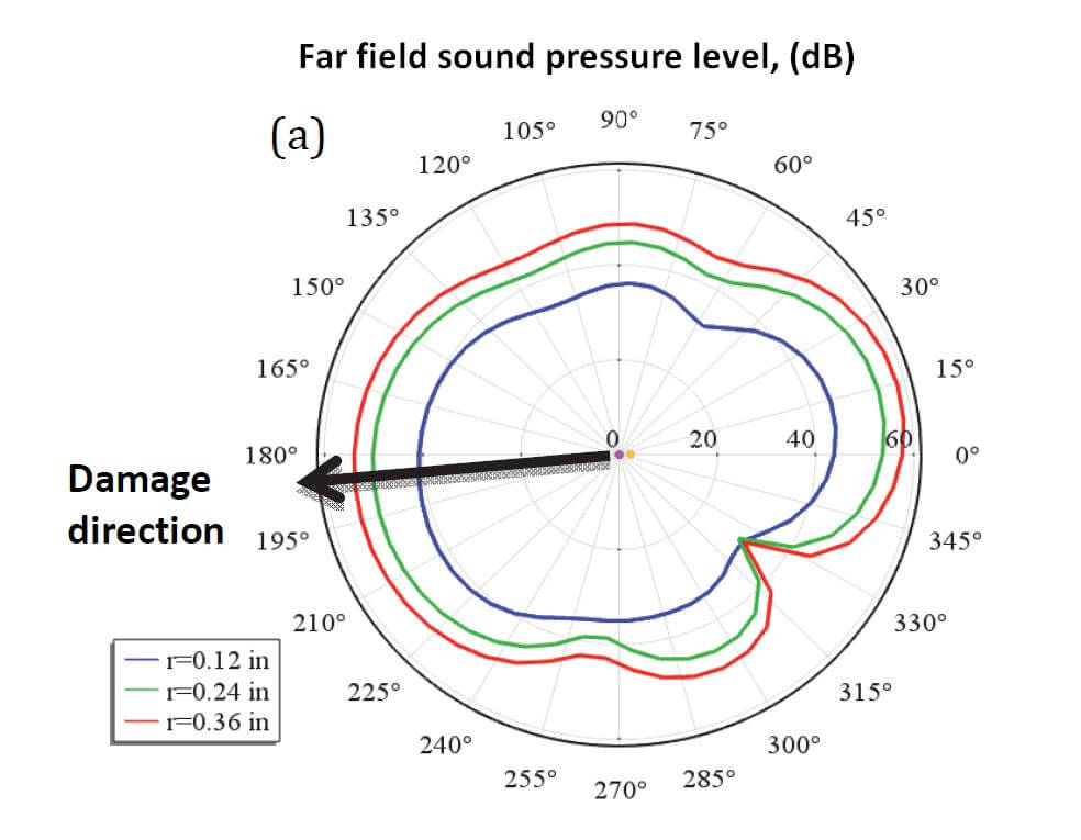
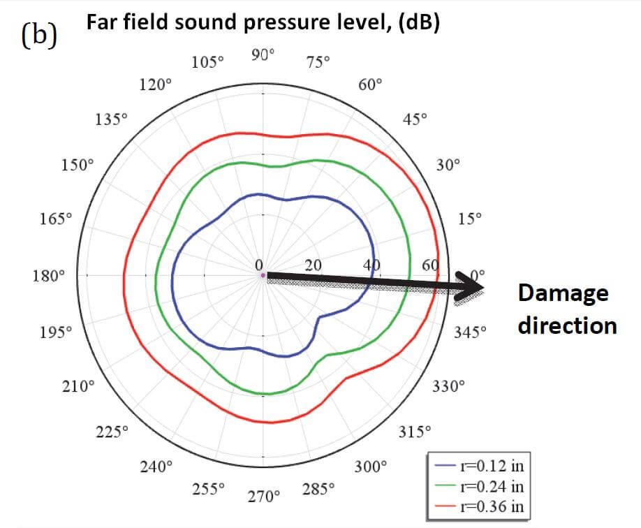
Finally, the influence of damage severity (size) on the sound directivity is investigated for the three separate regions on the blade, root, midspan and the tip. All of these results are presented in Figure 4(a), 4(b) and 4(c), respectively.
The results shown in Figure 4 indicate the fact that a midspan hole would create the highest sound pressure levels in general, slightly trailed by a root hole. The effect of hole size on the radiated sound pressure level is also the highest for the midspan hole. In the absence of any external excitations (such as wind flow), this is expected as the monopole source is position closer to the midspan region as it was previously shown in the Comparison of far field plot (a).
Conclusion
In this study, the multi-physics modeling capability of COMSOL was used to understand the influence of damage on the sound radiated by a subscale wind turbine blade actively excited from inside using a virtual monopole type sound source. Two separate virtual microphones were located, one inside the other outside of the subscale blade, emulating an active acoustic excitation source to be used in a real application. In the absence of the realistic wind-flow excitations in this simplified study, the results indicate that the location of the damage has more impact on the radiated sound levels compared to the size of the damage, under the assumption that the damage size is reasonably small. The directivity analysis showed a cavity internal microphone close to the root section and an external (outside the blade) microphone location underneath the nacelle makes the most sense in order to receive relatively high signal-to-noise ratio. This study will be complimented with an experimental investigation to better understand the influence of wind noise on the overall sound pressure level distribution around the blades and the effectiveness of the current approach on damage detection.
For further reading
[1] 2015 U.S. Wind Industry Market Reports, AWEA. [2] V. Arora, Y. H. Wijnant, A. de Boer, “ Acoustic-based damage detection method”, Applied Acoustics, 80, pp. 23-27, 2014. [3] W. Yang, “Testing and Condition Monitoring of Composite Wind Turbine Blades,” Recent Advances in Composite Materials for Wind Turbine Blade, Hong Kong: World Academic Publishing, pp. 147-169, 2013. [4] R. W. Hyers, J. G. McGowan, K. L. Sullivan, J. F. Manwell, and B. C. Syrett, “Condition monitoring and prognosis of utility scale wind turbines,” Energy Materials 1(3), pp. 187-203, 2006. [5] Z. L. Kahn-Jetter, T. C. Chu, “Threedimensional Displacement Measurements Using Digital Image Correlation and Photogrammic Analysis”, Experimental Mechanics, 30 (1), pp. 10–16, 1990. [6] M. Ozbek, D. J. Rixen, “Optical Measurements and Operational Modal Analysis on a Large Wind Turbine: Lessons Learned,” Shock and Vibration, Vol. 5, pp. 257-276, 2011. [7] M. Ozbek, D. J. Rixen, O. Erne and G. Sanow, “Feasibility of Monitoring Large Wind Turbines Using Photogrammetry,” The 3rd International Conference on Sustainable Energy and Environmental Protection, SEEP 2009, Vol. 35, No. 12, pp 4802-4811, 2010. [8] M. Ozbek, F. Mengt, D. J. Rixen, and M. J. L. Van Tooren, “Identification of the Dynamics of Large Wind Turbines by Using Photogrammetry,” Structural Dynamics and Renewable Energy, Vol. 1, pp 351-359, 2011. [9] M. Ozbek, D. J. Rixen, “Operational Modal Analysis of a 2.5mw Wind Turbine Using Optical Measurement Techniques and Strain Gauges,” Wind Energy, 16, pp. 367-381, 2013. [10] J. Carr, J. Baqersad, C. Niezrecki, P. Avitabile, “Dynamic Stress-Strain on Turbine Blade using Digital Image Correlation Techniques, Part 1 – Static Calibration”, Proceedings of the Thirtieth International Modal Analysis Conference, Jacksonville, FL, Feb 2012. [11] J. Carr, J. Baqersad, C. Niezrecki, P. Avitabile, “Dynamic Stress-Strain on Turbine Blade using Digital Image Correlation Techniques, Part 2 – Dynamic Measurements”, Proceedings of the Thirtieth International Modal Analysis Conference, Jacksonville, FL, Feb 2012. [12] C. Niezrecki, P. Avitable, J. Chen, J. Sherwood, T. Lundstorm, B. LeBlanc, S. Hughes, M. Desmond, A. Beattie, M. Rumsey, S. M. Klute, R. Pedrazzani, R. Werlink, J. Newman,”Inspection and monitoring of wind turbine blade-embedded wave defects during fatigue testing”, Structural Health Monitoring, pp. 1-15, 2014. [13] K. Aizawa, P. Poozesh, C. Niezrecki, J. Baqersad, M. Inalpolat, G. Heilmann, “An acoustic-array based structural health montoring technique for wind turbine blades”, Structural Health Monitoring and Inspection of Advanced Materials, Aerospace, and Civil Infrastructure, SPIE Vol. 9437, 94371P 1-17, 2015. [14] J. Tipperman, F. Lanza di Scalea, “Experiments on a wind turbine blade testing an indication for damage using the casual and anti- casual Green’s function reconstructed from a diffuse field”, SPIE Vol 9064 90641-1, 2014. [15] H. Boukabache, C. Escriba, S. Zedek, J. Fourniols, “Wavelet Decomposition based Diagnostic for Structural Health Monitoring on Metallic Aircrafts: Case of Crack Triangulation and Corrosion Detection”, International Journal of Prognostics and Health Management, ISSN 2153-2648, 2013. Excerpt from the Proceedings of the 2015 COMSOL Conference[16] Kai Aizawa, and Christopher Niezrecki, “ wind turbine blade health monitoring using acoustic beamforming techniques”, The Journal of the Acoustical Society of America, 135(4), 2392-2393, 2014. [17] E. Pierro, E. Mucchi, L. Soria, A. Vecchio, “On the vibro-acoustical operational modal analysis of a helicopter cabin”, Mechanical Systems and Signal Processing, 23, pp. 1205-1217, 2009. [18] R. Farshidi, D. Trieu, S.S. Park, T. Freiheit Non-contact experimental modal analysis using air excitation and a microphone array Measurement, 43, pp. 755–765, 2010. [19] M. A. Rumsey, J. A. Paquette, “Structural Health Monitoring of Wind Turbine Blades,” Smart Sensor Phenomena, Technology, Networks, and System, Proc. of the SPIE, 2008. [20] M. J. Sundaresan, M. J. Schulz, and A. Ghoshal, “Structural Health Monitoring Static Test of a Wind Turbine Blade,” National Renewable Energy Laboratory Report, 1999. [21] B.M. Fazenda, “Acoustic Based Condition Monitoring of Turbine Blades,” ICSV 18, Rio de Janeiro, Brazil, pp.1-8, 2011. [22] B. M. Fazenda, D. Comboni, “Acoustic condition monitoring of wind turbines: tip faults,” The 9th International Conference on Condition Monitoring and Machinery Failure Prevention Technologies, London, 2012. [23] R. O. Stearman, G.H. Schulz, and S.M. Rohre, “Aircraft damage detection from acoustic and noise impressed signals found by a cockpit voice recorder,” J. Acoust. Soc. Am. 101, 3085, 1997. [24] H. F. Lam, C.T. Ng, Y. Y. Lee, and H. Y. Sun, “System identification of an enclosure with leakages using a probabilistic approach,” Journal of Sound and Vibration, 322, pp. 756-771, 2009. [25] S. Kim, D. E. Adams, H. Sohn, G. Rodriguez-Rivera, N. Myrent, R. Bond, J. Vitek, S. Carr, A. Grama, J. J. Meyer, “ Crack detection technique for operating wind turbine blades using Vibro-Acoustic Modulation”, Structural Health Monitoring, Vol. 13(6), pp. 660-670, 2014. Excerpt from the Proceedings of the 2015 COMSOL Conference
Filed Under: News, O&M