Editor’s note: This transcript comes from a webcast with Rob Budny, president of RBB Engineering, a consultancy providing services to the wind industry. Mr. Budny is a mechanical engineer, with 20 years of experience, 11 of them in the wind industry. He spent 8 years at a major wind turbine OEM where he led the mechanical engineering functions. He’s also the co-author of a scientific paper on axial crack failures and wind turbine bearings that won the 2015 STLE Bisson award for best published paper.
Interested readers can watch the webcast at: http://goo.gl/h28RTf. All the webcast slides are available for download and a few are included here.
Let’s start with the function of a pitch bearing, which is to allow for variable pitch position of the turbine blade and to transmit blade loads into the hub. These loads include axial, radial, and moment components that are constantly changing in direction and magnitude. That’s actually quite challenging for the bearing to handle.
Inside a pitch bearing
The architecture of the pitch bearing consists of an inner ring, an outer ring, two rows of balls, either a cage or spacers, and also seals.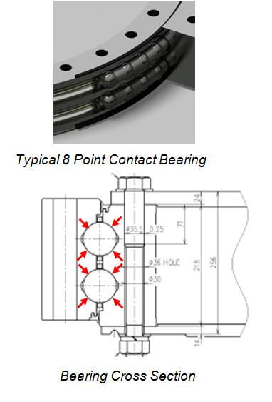
This upper figure shows a typical pitch bearing. They’re referred to as 8-point contact bearings. The drawing shows a cross-section of the bearing and you can see that each ball contacts the inner and outer ring in a total of four places, hence the term 8-point contact bearing.
There are many design challenges for a pitch-bearing application. One, for example,
is that the blade the bearing supports will spend a long period in a fixed position. If a bearing isn’t moving, then it’s not developing an oil film and that has negative implications for the performance of the bearing, as will be shown.
When the bearing does move, the amplitude of the motions are quite small so the bearing is turning back and forth. It’s not making full rotations and likewise, that has implications for the oil film. It makes it difficult for the bearing to develop an oil film between the balls and the bearing rings.
The bearing is subjected to high loads, which in turn result in high stresses in the bearing. The bearing is mounted to flexible mounting structures, being the blade and the hub. Because the structures that the bearing is bolted to are not very stiff, you can get large deflections between the inner ring of the bearing and the outer ring of the bearing. That presents some challenges to the bearing.
You have exposure to the environment, so the bearing must withstand moisture and also abrasive materials in the environment. The bearing also has cost constraints. As we all know, the wind turbine industry is a very cost sensitive industry and so for any component to make its way into the turbine, it has to be made at the lowest feasible cost.
These are some of the challenges associated with designing and manufacturing a pitch bearing. For example, what are the common failure modes that pitch bearings experience?
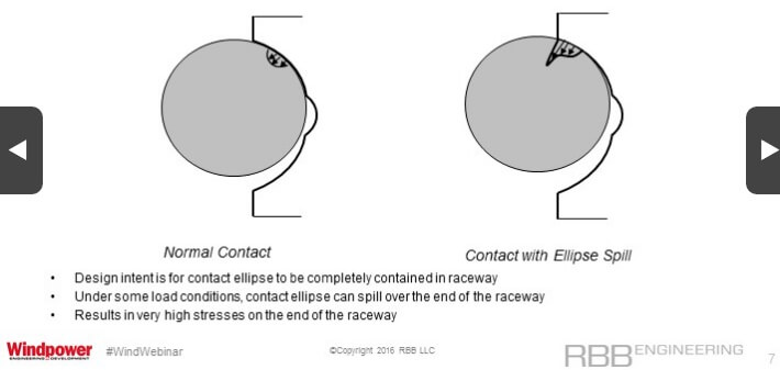
The first one is ellipse spill. The design intent of a pitch bearing is that the contact ellipse should be completely contained in the raceway. Here’s a schematic of a normal contact and then here I’m showing where the contact zone is fully contained within the raceway.
Thursday, June 9, 2016, in Houston. ( Nick de la Torre / )
Under some load conditions, that contact ellipse can spill out over the end of the raceway, illustrated in the schematic. When that happens, there’s a high stress at the edge of the raceway. This can have consequences.
Here’s an example of a pitch bearing that has damaged from ellipse spill.
Thursday, June 9, 2016, in Houston. ( Nick de la Torre / )
The contact spilled over the edge of the ball path, creates high stresses and a spall that developed in that location.
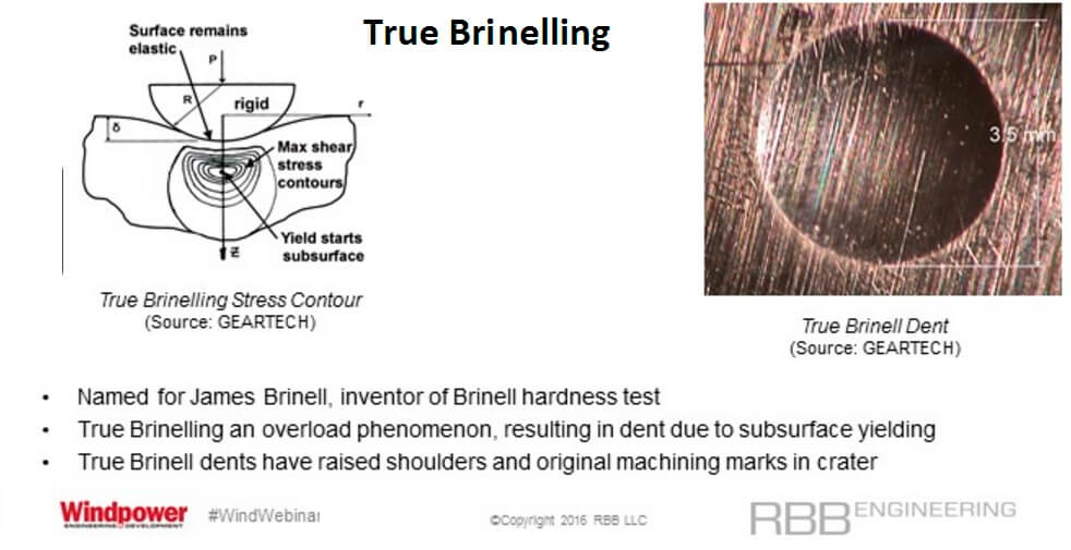
The next failure mode is called true Brinelling (above). This is named after James Brinell, the inventor of the Brinell hardness test. True Brinelling is an overload phenomena that results in a dent on the surface due to subsurface yielding. Here’s a schematic of this situation. When the loads on the ball, represented by P, R, exceed the capacity of the bearing, the subsurface of the bearing, actually the shear stress in the subsurface of the bearing, causes that material to yield.
Yielding doesn’t occur at the surface. It occurs actually at the subsurface. The true Brinell dent will have raised shoulders and also you’ll have the presence of the original machining marks in the crater.
A dent crater is to the right in the image. You can see, outside of the crater you can see the machining marks and inside the crater as well you can also see the machining marks. This is one telltale signs that what you have a true Brinell dent, that it’s not a wear mode, but it’s true Brinelling. You can still see the presence of the machining marks in the crater.
There’s another phenomena called false Brinelling. False Brinelling is named because the wear scar can actually look very similar to the indentation from true Brinelling. However, the mechanism is different. The mechanism is a type of adhesive wear, which occurs under boundary lubrication. Boundary lubrication is where you don’t have an oil film separating the surfaces, but you do have some of the chemical additives in the oil, which are providing minimal protection.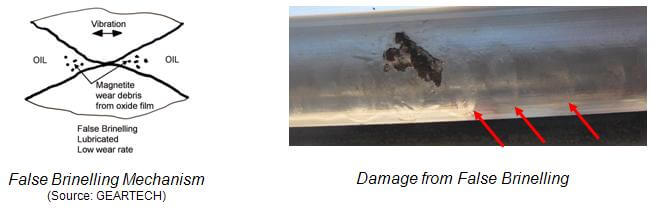
A schematic of the false Brinelling mechanism appears to the left. You have the two components in contact. You don’t have the lubricant oil film and you have a small amplitude of vibration. When this happens, you generate a form of iron oxide which is known as magnetite. This creates a wear scar that does not have raised shoulders and the machining marks in the wear scar are worn away. Now this wear scar is harmful and is the debris which is generated. It’s also abrasive.
Here’s an example of a pitch bearing. You can see some of the false Brinell marks, which are highlighted by the arrows. The false Brinelling wear scar can look like a true Brinelling indentation, but it’s actually something quite different.
The next failure mode I’d like to talk about is fretting corrosion, which is actually a similar failure mode to false Brinelling. The name derives from the appearance of the fretting corrosion wear scar, which looks like rust. Fretting corrosion is a severe form of adhesive wear, which occurs under completely unlubricated conditions.
Here’s a schematic of fretting corrosion. It starts off as false Brinelling, but the magnetite debris builds up and acts as a dam so that no lubricant can make its way back into the contact zone. At that point, the oxide layer on both surfaces has worn off and produces steel-on-steel contact. A form of iron oxide is generated, called hematite, which is orange in color.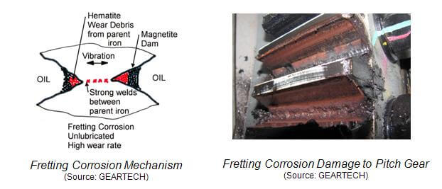
Here’s an example of a fixed gear which has had damage from fretting corrosion, where the same phenomena affects the internal components of the pitch bearings as well.
Fretting corrosion has a high rate of wear. It’s extremely damaging. It also generates a tremendous amount of abrasive materials so the wear scar that is created is itself very damaging, as is the wear debris, which is captured in the grease and then results in abrasive wear throughout the rest of the bearing.
The wear scar itself can serve as the failure initiation point and again, the wear debris is also very abrasive in nature.
Macropitting is the next failure mode. Here’s an example of a pitch bearing with macropits on the roller path.
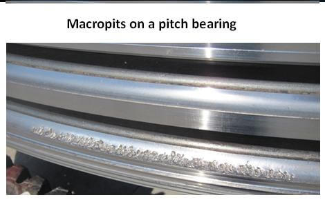
Macropits can have several root causes. Subsurface shear stress can cause cracks, which will eventually surface and coalesce. You can also have the presence of non-metallic inclusions in critical locations of the bearing, which will result in macropits. Or you can have surface defects, a PSO, which is a point source origin, or GSC, which is a geometric stress concentration, can serve as the crack initiation site.
All these root causes can affect pitch bearings, but the surface defect cause would be the most common. When the roller path surface breaks down, the bearing becomes completely nonfunctional.
Another failure mode: cracks in the bearing ring. These bearing rings have holes, either for grease fittings or for handling features. The presence of these holes act as stress risers. They increase the nominal stress in the bearing ring. These features can initiate cracks, which would then result in the failure of a bearing.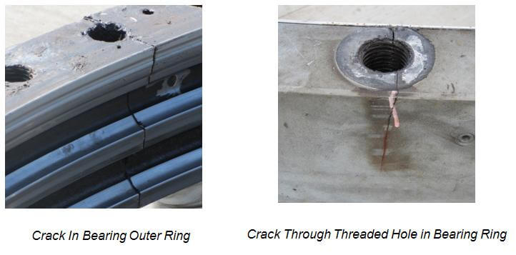
Here’s an example of a bearing outer ring with a crack and the crack started in a threaded hole. Similarly here again is another bearing outer ring with a threaded hole which caused a crack to develop.
The best way to determine the health of a bearing is through a grease analysis. The grease analysis can provide the most advanced warning of a pitch bearing deterioration. When the grease sample is taken, the size, the shape, and the amount of wear particles can be interpreted to determine both the severity and the type of wear in the bearing.
Here’s an example of a grease sample.
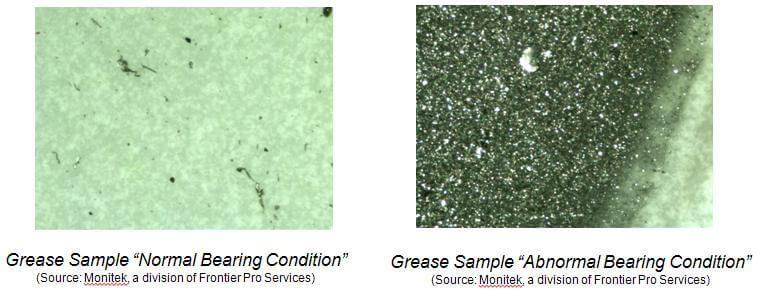
In this test, a fixed amount of grease is removed from the bearing and is pushed through a filter patch. The number and size of the particles is counted. This figure on the left is from a bearing in a normal condition. The figure on the right is the same quantity of grease, subjected to the same protocol, but you can see that there is a vastly larger number of wear particles and that they’re much larger in size.
With respect to failure prevention, the further upstream it starts, the more you can do to prevent failures. Let’s start with the designer procurement specification. This could really be a first layer of protection against failures. Consider requiring a fully flexible analysis, including the effects of the hub and blade.
Historically, manufacturers would typically do an analysis of the stress state in the bearing. But they would assume a rigid hub and blade, and of course, they are not rigid. The compliance of those structures affects the stresses in the bearing. I would suggest considering performing a fully flexible analysis on the bearing.
Here’s an example of a pitch bearing on a hub that includes compliance of the hub in the analysis.
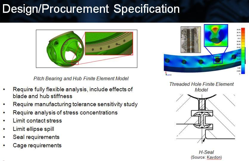
I would also suggest requiring a manufacturing tolerance sensitivity study. This 8-point contact bearing requires extreme precision so all 8 points of the bearing are in contact. To the extent that manufacturing tolerances allow for variations in the tolerance, they should be studied and include the effects on the stress in the bearing. I would suggest you consider putting that into a designer procurement specification for pitch bearings.
Here’s an example of such an analysis. Also consider limiting the contact stress in your designer procurement specification and also limit the extent of ellipse spill. Ideally, you wouldn’t allow any ellipse spill, but if you choose to do so, limit the extent and also the number of load conditions, which result in ellipse spill.
Lastly, seal requirements. A well function seal keeps grease in and keeps water and contaminants out. An accompanying image (Above and lower right in Design/Procurement Spec) provides an example of a seal from SKF Kaydon. It’s called an H-Seal and works well reacting internal pressures against grease. That helps pressurize the bearing and purge grease out. It also tolerates relatively large deflections between the inner and outer ring and that keeps grease in and keeps the contaminants out when the bearing is exposed to high loads and large deflections.
The cage requirements, there have been lots of problems with cages in pitch bearings so that’s something that the specifications should require a cage, should comment on the strength of the cage, and the allowable stress in the cage as well.
The next line of defense would be manufacturing quality. Work with your manufacturer to ensure the accuracy of the component geometry.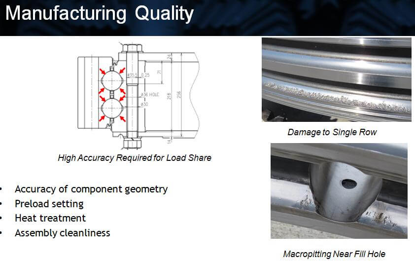
For example, consider the cross section in the accompanying image of an 8-point contact bearing. Two balls are independent of each other and each touches the inner and outer ring in four places for a total of eight places. The precision required in terms of the size of the balls, the location of the ball path, the geometry of the ball path, all must be extremely precise, otherwise the bearing will not contact in eight places as designed.
Another image here shows a pitch bearing that failed. The top row is completely undamaged while the bottom row is completely spalled. In this case, the row-to-row spacing was incorrect so only one row of balls was carrying load. The bearing failed because of a manufacturing accuracy issue.
Another example of a manufacturing quality-related issue shows a fill hole (above, right) a feature required to install the balls into the bearing. To manufacture this fill hole, this area of the bearing cannot be hardened. So the bearing drawing will require that this area around the fill hole be relieved so the contact stresses are low. Also, the fill hole will be located in a relatively low-stress area of the bearing. In this case, that didn’t happen and the bearing spalled at the soft locations near the fill hole.
Another important manufacturing quality-related item is accurately setting the preload. These bearings are preloaded and to perform the way that they are intended, the preload must be set correctly. Also these bearings are induction heat treated. It is actually a sensitive and temperamental process prone to error. So you must make sure that the manufacturer has good process control over the heat treatment process.
Lastly, assembly cleanliness. Abrasive wear is a big killer of pitch bearings so it’s important to build a clean bearing in the factory before it’s even moved out into the field. These are manufacturing quality-related issues. If you work with your manufacturer, they can help ensure that any pitch bearing you get will give you good, long service.
Selecting a grease
This is probably the most important thing you can do to help improve the reliability of pitch bearings already in service. Important things to think about, in terms of selecting grease, would include the base oil viscosity, the tendency for oil to separate from the grease, how well the grease pumps, the low temperature viscosity, mechanical stability, and last and certainly not least, but a resistance to fretting and false Brinelling. There are a wide variety of fretting and false Brinelling resistance from greases and the problem is one of the main killers of pitch bearings. It’s important to pick a grease that is good at preventing fretting and false Brinelling.
A few tests can be done to help characterize fretting resistance. For example, the Riffel test developed by Exxon Mobile.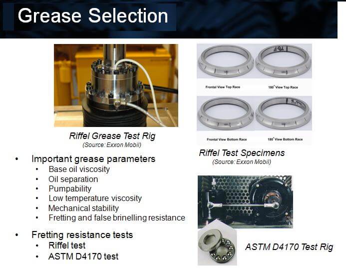
The figure on the right of the picture shows test specimens that have been subjected to the Riffel test and a depth produced by the test. The extent of the wear scars is measured which characterizes the performance of the grease. There’s also an ASTM standard test for testing the fretting resistance.
Finally, autolube systems are another lubrication-related item. The accompanying schematic of an autolube comes from SKF. This is a schematic of either the manual lubrication process or the automatic lubrication process. The manual lubrication process is shown in red. The manual lube puts in large quantities of grease, but relatively infrequently, whereas with an autolube, the system constantly puts in small quantities of fresh grease, which make it more likely that the pitch bearing has a clean charge of grease in the contact area.
In terms of future design trends, both wind turbine OEMs and bearing manufacturers understand that as rotors are getting longer and loads are going up, we’re reaching the limit of the 8-point contact bearings’ ability to be used in wind turbines. One design from Kaydon is being considered. It is a two row, angular-contact ball bearing. This design is much less sensitive to manufacturing tolerances. Each ball only contacts the inner and outer ring in just two places. It’s much less sensitive to manufacturing tolerance and it allows for a much longer contact ellipse making it less sensitive to ellipse spill.
A similar concept uses rollers instead of balls. Roller bands have a higher load capacity than do ball bearings.
A few more resources
For more information on this topic, look to the RBB Engineering website resources page. It has technical papers and presentations from our conference presentations and free to download. You don’t need to provide any information. They’re all listed on the resources link of our homepage. We also publish with Bob Errichello of GearTech at GearboxFailure.com. It may be the most comprehensive source of gear and bearing reliability information on the internet. We’ve got lots of information there, lots of resources, a few of which we sell, but the vast majority of which are available for free download.
Other good resources that I would recommend would be the AWEA recommended O and M practices, the RP 814 Wind Turbine Pitch Bearing Grease Sampling and Procedures, which is quite good, and ASTM standard, D7690, for how to perform a grease and oil particle analysis.
Filed Under: Bearings, O&M