Wind-turbine cable terminations have unique requirements for seismic bracing, resistance to a range of vibration frequencies, and an ability to function reliably in harsh environments. There are also different ways to crimp connectors to conductors. Identifying the proper installation method is easily done with the right tools.

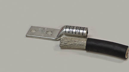
Left: A reliable electrical performance, the indent-style crimp removes almost all air gaps from the conductor as the strands are formed tightly together inside the connector.
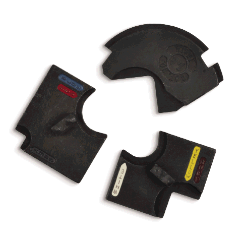
Center: The T&B Blackburn Color-Keyed system lets an installer quickly determine the proper die by matching the color code to the connector. The hex-style crimp gives greater electrical performance and calibrated pullout strength.
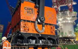
Right: The T&B Hex-Flex Die System maintains traditional color-coding and die embossing for easy identification and inspection. The system also produces higher pullout values across all types of flex cables and reduces the number of crimps required on most connectors.
Wind-turbine applications put unique demands on cables that transmit the generated power to the power conversion equipment, and through to the step-up transformer and grid interconnection switchgear. The space within a nacelle is at a premium–the area must accommodate conversion and termination equipment, as well as auxiliary power resources, such as transformers and a variety of control circuits. Cables there must be capable of tight bends and turns, and to carry the ampacity (ampere capacity) of the generators. For that reason, designers prefer flexible diesel locomotive (DLO) cable in the restricted space up-tower. It is capable of carrying high voltages–from 690Vac and 2,000 A.
However, there is some confusion over the proper connectors and lugs to use with flexible cable. The National Electrical Manufacturers Association (NEMA) issued bulletin No. 105 advising the industry that mechanical set-screw connector lugs and terminals are not intended for use with fine-stranded conductors.
Although mechanical set-screw connectors are commonly used in applications where solid, B or C-Code cables are used, they are not recommended for use with fine-stranded flexible conductor cable because the mechanical connection can break the fine strands, resulting in overheating and wire pullout. NEMA calls for compression-type connectors when terminating fine-stranded flexible conductor cable.
This article provides guidelines for selecting the proper compression connectors and terminals for these applications, as well as the proper method for installing these connectors to ensure a secure, trouble-free termination.
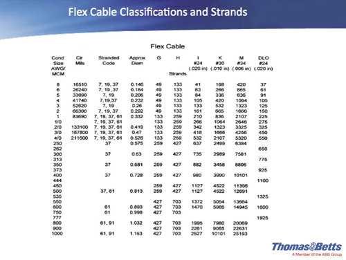
Flex cable classifications and strands let technicians match the connectors to the proper cable type.
Matching the connector to the cable
Flexible-conductor cable, such as DLO, commonly known as flex cable, has become more widely used in the past few years for up-tower power transmission. Flex cable is easier to maneuver in tight quadrants, particularly with sizes beginning at 250 MCM, as well as when cable movement is prevalent in wind-turbine applications. There are many different flex cable classifications and strands, so it is important to match the connector to the cable.
Some connectors, like those from Thomas & Betts, are dual rated for code and flex cable, while other manufactures require a different connector for each application. The connectors should clearly identify the proper application, whether B or C-Code, or flex-type cables. This is in compliance with UL standard 486 A–B which states, “A connector, a unit container, or an information sheet packed in the unit container for a connector tested with conductors other than Class B, single input wire, or Class C stranding shall also be marked with the conductor class or classes, and the number of strands.”
Compression connectors come in an almost limitless variety that includes one and two-hole lugs, butt splices, H-taps, and C-taps, to name a few. They are also available for copper, aluminum, or copper-clad aluminum conductors. Compression connectors offer a number of advantages over mechanical connectors: the connection is permanent when properly installed with the correct tooling. The connection is irreversible which is sometimes required for grounding applications. The low-profile crimps are easy to insulate. Some connectors are also available with an oxide inhibitor.
A disadvantage is that each conductor size requires its own connector and crimp tooling to make a properly calibrated connection.
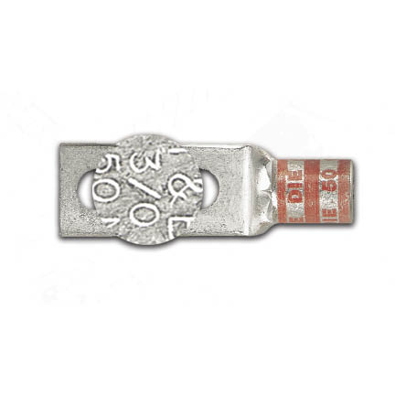
In compliance with the UL standard, connectors will be marked with its conductor classes and the number of strands. For the connector pictured, conductor class is 3/0.
An overview of crimping styles
When it comes to installing compression connectors, electrical contractors traditionally had two choices of crimping methods: the indent-style crimp, made by die-less compression tools, or the hex-style crimp, made by compression tools equipped with interchangeable hex dies.
When correctly performed with a proper tool that corresponds to the size of cable and connector, the indent-style crimp offers reliable electrical performance and an approved, calibrated pullout resistance. With an indent-style crimp, the connector is left with rounded edges and the capability to produce an arc flash. Also, most air gaps are removed from the conductor as the strands are formed tightly together inside the connector. The indent-style crimp, however, does not provide the ability to inspect for a proper crimp.
The industry standard hex-style crimp has long been preferred for crimping compression connectors onto B and C-Code copper, and aluminum or copper cables up to 1,000 MCM. One system lets the installer quickly determine the proper die by matching the color code to the connector. The hex-style crimp provides superior electrical performance and a calibrated pullout strength. Additionally, hex dies emboss the die code onto the connector for easy inspection and verification of a proper crimp after installation.
A recent, third method of attaching connectors to flexible conductors combines the best of the indent and hex-style crimp: superior calibrated pullout ratings and the ability to inspect for a proper QA/QC measured and documented crimp. The recent system consists of standard color-keyed hex die halves and an indenter. The hex portion keeps the traditional color-coding and die embossing for easy identification and inspection. The indenter is round, smooth, and produces the higher pullout values across all types of flex cables. Due to the higher pullout values created by the system, it also reduces the number of crimps required on most connectors.
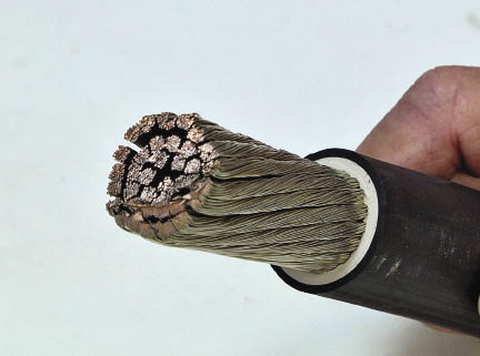
For installing a compression connector, the wire insulation must be stripped carefully to protect the conductors.
Steps for Proper Connector Installation
Properly installing a compression connector takes a few steps and is easily done with the right tools:
1. Read the quality procedures and prepare the cable
Strip the insulation carefully to avoid marring or cutting the conductors – check procedures prior to starting. Be careful to strip the insulation to the proper length so that the conductors can be fully inserted into the connector barrel, but not so long that it exposes bare wire or un-insulated cable.
Check wire schedule to ensure that the cable matches design criteria for ampacity and voltage. Compression connectors come marked indicating the proper application. These markings are clearly visible on the connector, as well as on product packaging and enclosed literature. Be sure to match the connector to the application.The connectors are marked with several important pieces of information (Read all applicable codes and regulations associated with this procedure.) For this example:
• Application by color and die code
• Wire size
• Crimp indicator bands
• Canadian Standards Association (CSA) or UL listings
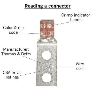
Most connectors are marked indicating the proper applications. The markings are readily visible and can also be found on product packaging and accompanying literature.
Connectors marked with just the cable size or “CU” should only be used on copper conductors. While connectors marked “AL( )” with a cable size should only be used on aluminum conductors. And connectors marked “AL( )CU” with the cable size may be used on aluminum or copper conductors.
A wide range of tools, from manual to battery-operated hydraulic crimping devices, make it easier to install compression connectors.
The color-keyed method simplifies the selection of the proper installing die to match the tool. Color-keyed connectors have colored bands or colored dots that correspond to the colored markings on the dies. Connectors and dies also have a die-code number marked or stamped on them. Dies have a code number engraved on the crimped surface.
Read all procedures, applicable codes, and regulations associated with this procedure. Locate the markings on the connector and die. Keep fingers away from the crimping mechanism. Insert the connector into the tool, then position and align the die and connector.
When making multiple crimps, make the first one nearest to the tongue and work toward the barrel end. Connectors are banded with color stripes to indicate the number and location of each crimp. The connectors are also marked with the die-code number at each compression location. When properly crimped, the die-code number will be embossed on the connector for easy inspection to determine if using the correct die and connector combination.
With the increasing use of fine-stranded, flexible conductor cable in wind turbine applications, take care to use the proper connector and connection method. Compression connectors should be used instead of mechanical connectors, while installers must ensure proper installation. By following the steps outlined above, electrical contractors will be following NEMA and UL-approved methods. WPE

Sammy Germany PhD
Market Development Manager –
Renewable Energy & Power Generation
Thomas & Betts
www.thomasbetts.com
Filed Under: Featured, News

