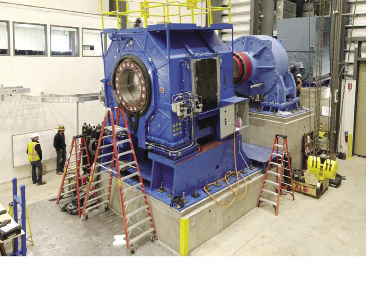
Progress on the 5-MW dyno is as recent as January. The large blue unit is the NTL. To its right is the dynamometer gearbox and behind that, the drive motor. The units mounted on a plane fixed at 5° to account for the nominal inclination of wind turbine drive lines.
The National Renewable Energy Lab in Golden, Colo. is getting close to cutting the ribbon on a 5-MW dynamometer that will allow testing new turbine drivetrains and equipment. “The 5-MW dynamometer and drivetrain testing facilities will complement the existing 2.5-MW dyno,” says NREL Senior Engineer, Hal Link. He discussed the progress of construction at a recent meeting of the Gearbox Reliability Collaborative.
Features include a non-torque loading (NTL) device that will provide loads, such as bending moments, with up to five degrees-of-freedom, in addition to torque. The NTL device has its own controls. The older 2.5 MW dyno has a limited, 3-degrees-of-freedom NTL.
The 5-MW dyno will also use a grid simulator to replicate grid problems such as low voltage and open circuits. Other responses of wind turbines to grid faults are driven by the rotor inertia. “During a grid fault there is suddenly no place to put the power, so you must make sure the rotor does not over speed. We can duplicate that condition in the dyno, and it is safer than testing in a wind farm where a rotor over-speed may result in turbine failure,” says Link.
Even the building that will house the new dyno will show improvements over the housing for the 2.5 MW dyno. “The new housing is
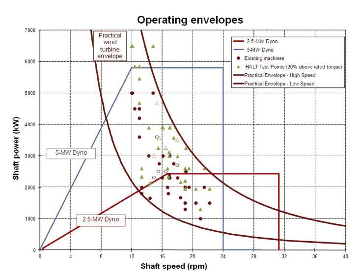
The 5 MW speed-power curve shows that at 12 rpm it can generate up to 5.8 MW. The new dyno expands the region previously allowed by the 2.5 MW dyno alone.
largerand taller and the door is offset so trucks can roll in. The door for the 2.5-MW unit is directly in line with the driveline, so it was impossible to get a truck in there to unload a big drive- train,” says Link. The smaller dyno was launched in 1998 and has tested about 15 drivetrains since then.
A controllable-grid interface, another feature, is essentially the power-electronic system. ”Most variable-frequency drives allow one control, speed or torque, but in this case we can do all sorts of things,” says Link. Many of its switches are programmable.
The controllable grid interface will let engineering teams test grid faults. It also permits testing at 50 and 60 Hz, and simulates high and low-voltage variations from nominal. These capabilities allow verifying a turbine’s power electronics systems.

A drive-through arrangement for long trucks would have been ideal, says Hal Link, but there was not enough money in the budget. However, drivers are adept at backing out. Two 75-ton cranes will lift 150 tons. The 300,000-lb capacity allows for a sizable gearbox and mainframe.
“It was built by ABB and they are willing to work with us to make sure this thing runs well in simulations. It will provide the short and open-circuit conditions that often wreak havoc with wind turbines,” he adds. The first drivetrain for test will arrive late spring or early summer. WPE
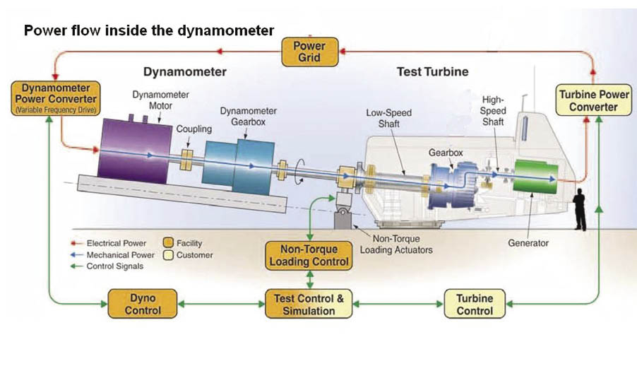
A variable-frequency drive will turn the dynamometer’s motor while a gearbox slows the motor’s speed to that of a typical turbine rotor. The non-torque loading device simulates rotor loads, other than torque, with five degrees-of-freedom. The equipment can drive a gearbox in test from low to high speeds. Generator output then goes to the grid by another device that could be a power converter for operation at variable speeds. Or, the converter could be swapped for a set of contacts that are frequently augmented with a soft start to reduce loads when a generator connects to the grid.
Filed Under: News, Turbines