Matt Caie, Mike Gassman, ERICO/ Solon, Ohio/ erico.com
The average lightning discharge releases 55 kWh in only 100 to 300 microseconds. This calls for effective methods of protecting blades on wind turbines along with their internal electrical and electronic systems.
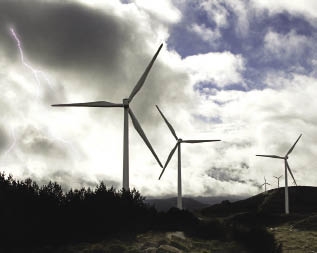
Updrafts in cumulonimbus clouds, 3 to 4-km deep, give rise to the separation of electric charges which leads to the lightning discharge.
Most wind turbines work in harsh locations, making them susceptible to damage from volatile weather. Lightning damage, particularly to wind turbines, is often attributed to inadequate direct-strike protection, incorrect or insufficient bonding and earthing (grounding), and insufficient transient protection.
In addition to a direct strike to a blade, high-energy over-current and over-voltage transients induced by direct and indirect lightning strikes can cause significant damage when these massive structures are left unprotected. The principles behind protecting wind turbines from lightning strikes are best appreciated with a basic understanding of the formation of lightning and the attachment process.
First, a primer on lightning
There are about 1,700 electrical storms active throughout the world at any time producing over 100 flashes per second. This equates to some 7 to 8 million strikes per day. Of these, about 90% are cloud-to-cloud discharges and the remaining are predominately cloud-to-ground strikes.
With increasingly complex and sophisticated wind turbine systems, a single lightning strike can result in significant physical damage and catastrophic failure. It can initiate fire, cause major electrical equipment failure and mechanical damage, and produce substantial loss of revenue through down-time.
Lightning develops when the upper atmosphere becomes unstable due to a convergence of a warm, solar-heated, vertical air column on a cooler upper air mass. These rising air currents carry water vapor, which, on meeting cooler air, usually condenses and gives rise to convective storm activity. Pressure and temperature are such that the vertical air movement becomes self-sustaining, creating the basis of a cumulonimbus cloud formation with its center core capable of rising to over 15,000 m.
To generate lightning, the cloud must be 3 to 4-km deep. Taller the cloud, the more frequent the lightning. The center column of the cumulonimbus can have updrafts exceeding 120 km/hr, creating intense turbulence with violent wind shears making them hazardous to aircraft. Updrafts also lead to electric charge separations which ultimately leads to the lightning discharge.
The earth’s surface is positively charged and the lower atmosphere takes on an opposing negative space charge. As rain droplets carry charge away from the cloud to the earth, the storm cloud takes on characteristics of a dipole with the bottom of the cloud negatively charged and the top of the cloud positively charged.
Waterfall studies show that fine precipitation acquires a positive electrical charge while larger particles acquire a negative charge. Updrafts in a cumulonimbus separate these charges by carrying the finer (positive) charges to high altitudes. The heavier negative charges remain at the base of the cloud, giving rise to the observance that about 90% of all cloud-to-ground discharges occur between a negatively charged cloud base and positively charged earth (i.e. negative lightning).
The separation of electrical charge within a cloud lets electric potentials increase to a point where a neutralizing discharge must occur. The main concern for lightning protection is the cloud-to-ground discharge. This is a two-staged process. One discharge initiates from the cloud and another from the ground or structure.
Ionization at a cloud bottom cloud forms corona discharges. These are brought on by the ionization of a fluid surrounding a conductor and occur when the electric field strength (a potential gradient) exceeds a value, but conditions are insufficient for arcing or a complete electrical breakdown.
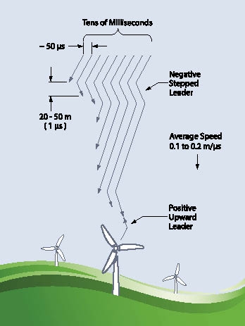
A leader or initial discharge begins propagating toward the ground. Wind shear tends to blow away ionized air, momentarily halting the progression until sufficient ionization develops to allow the discharge to progress in the next discrete step. This stepped leader progresses rapidly toward the ground and may branch into many “fingers” as it reaches the ground.
As the leader approaches the ground, the electric field rapidly increases, accelerating local ground ionization. At this time, the potential difference between leader and earth may be up to 107 V, resulting in breakdown of the air.
The ground discharge (streamer) then begins moving up (becoming an upward leader) toward the down leader, intercepting at some tens of meters above ground. In the case of a wind turbine, the structure can be visualized as a lightning rod to the earth with the interception taking place over one hundred meters above the earth.
After the upward and down leaders generate an ionized channel, there exists a low-impedance path between cloud, turbine, and ground which initiates the main discharge or return stroke. This is characterized by a rapidly increasing electric current whose rate-of-rise is typically 1,010 A/s. Peak currents averaging around 30 kA are typical, with minimum currents of 1 to 3 kA. Maximum discharges exceeding 200 kA have been recorded.
It is also possible to have consecutive discharges down the same channel. This happens when the initial discharge neutralizes the localized charge cell in the cloud. Nearby cloud cells then flash across to the ionized channel and use it to discharge to ground. In this manner, up to 16 discharges have been observed using the one channel.
A statistical approach
The average energy released in a discharge is 55 kWh, a significant amount of energy by modern generation standards. The danger of the discharge lies in the fact that all of the energy is expended in only 100 to 300 microseconds, and the peak discharge current is reached in only 1 to 2 microseconds. Channelling the energy from the wind-turbine blade through the nacelle and tower to ground takes proper design coordination.
The difference between positive and negative lightning is that the positive lightning leader is not stepped nor are there multi-strikes. There is only one return stroke, after which a continuous current flows to discharge the cloud.
Because lightning is a natural phenomenon, a statistical approach is useful in its analysis and the design of protective systems. Data from the International Council of Large Electrical Systems (CIGRE) indicates that:
• 5% of negative lightning impulses exceed 90 kA (average is 33 kA)
• 5% of positive lightning impulses
exceed 250 kA (average is 33 kA)
• 5% of negative re-strikes exceed a
rate of current rise 161 kA/µs
The IEC 62305 series introduces four lightning protection levels (LPL) with design rules based on a lightning protection system that guards against strikes of minimum and maximum values. Probability of exceeding limits shows probabilities that these maximum and minimum values may be exceeded.
For example, in LPL I, there is only a 1% probability that lightning would be greater than the design limit of 200 kA (2% for LPL II upper limit of 150 kA and 3% for LPL III and IV limit of 100 kA). LPLs are selected by the engineer based on a risk assessment defined by the appropriate IEC standard.
While the air termination, conductor, and earth-termination size are sufficient to withstand the current at the upper limits, of main consideration is the minimum values and the ability of the lightning-protection system to intercept these smaller strikes.
As a lightning down leader approaches the ground or a wind-turbine structure, the electric field is such that the ground or structure launches an intercepting streamer. The larger the electrical charge, the greater this final jump or striking distance.
A formula using minimum current levels for various lightning protection levels (the previous table) indicate a radius for what’s called the Rolling-Sphere Method (RSM).
It uses a sphere of radius equal to the striking distance that is usually employed to visualize a likely stroke termination point. Application of RSM involves rolling an imaginary sphere of a prescribed radius over the air termination network. The sphere rolls up and over air terminals, shield wires, and other grounded metal objects intended for direct lightning protection. A piece of equipment is protected from a direct stroke if it remains below a curved surface of the sphere by virtue of the sphere’s being elevated by air terminals or other devices. Equipment that touches the sphere or penetrates its surface is not protected.
Generally, a higher protection level requires a smaller rolling-sphere radius for the lightning protection system to capture smaller lightning strikes. Therefore, the higher the protection level, the greater the material requirements. Strikes of less than 3 kA are rare and typically would not be expected to damage a wind turbine.
No lightning protection system is 100% effective and a system in compliance with the standard does not guarantee immunity from damage. Lightning protection is an issue of statistical probabilities and risk management. A system in compliance with the standard should statistically reduce the risk to below an acceptable threshold. The IEC 62305-2 risk-management process provides a framework for this analysis.
Risks to people and structures
Effective lightning protection must control a variety of risks. While the discharge current of a lightning strike creates a number of electrical hazards, thermal and mechanical hazards also must be addressed. For example, the risk to people and animals include direct strike, step potential, touch potential, side flash, and secondary effects, such as asphyxiation from smoke or injury from fire, structural dangers (such as falling masonry from a strike point) and unsafe conditions, such as water ingress from roof penetrations causing electrical or other hazards, and failure or mal-operation of processes, equipment, and safety systems.
Furthermore, risk to structures and internal equipment include:
• Fire or explosion or both triggered by
a direct strike or electrical arcing of discharge current within a structure
• Fire or explosion or both triggered by
ohmic heating of conductors or
arcing due to melted conductors
• Punctures of structure roofing due to
plasma heat at the lightning strike point
• Failure of internal electrical and
electronic systems
• Mechanical damage, such as dis- lodged materials at strike point.
Filed Under: Safety

