OSHA is stepping up wind-turbine inspections to prevent worker injuries due to arc flash and other hazards. Special protective relays activated by light work well to mitigate the effects of such hazards.
By: Tony Locker, Littlefuse, Inc., www.littlefuse.com

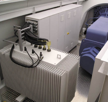
The primary and secondary terminals of a transformer in a nacelle may be monitored with light sensors as part of an arc-flash detection and protection system.
OSHA has stepped-up inspections as a result of several arc-flash events associated with wind turbines. The organization reports the investigation of 32 arc-flash accidents that occurred in 2009 at wind farms. According to the agency, total industrial arc-flash incidents cause about 80% of electrically related accidents and fatalities among qualified electrical workers. In 2010, OSHA investigated one such event that resulted in severe burns to a wind-farm technician and proposed fines of $378,000 for the employer, a service and maintenance company to the wind-energy industry.
Starting in 2012, OSHA will be targeting the wind-energy industry with one of its National Emphasis Programs (NEP). The agency announced that operation and maintenance of wind turbines are subject to the same regulations applied to traditional power-plant operations. In this regard, OSHA will apply 29 CFR 1910.269, that, among other things, requires safety procedures and use of personal-protective equipment and clothing consistent with NFPA 70E rules.
All this is good for workers in the industry and can save employers money in the long run. Industry estimates place average costs for the medical treatment of arc-flash survivors at around $1.5 million, and associated litigation costs up to $10 million. Still, inspections and fines do nothing to mitigate the effects of an arc-flash. Fortunately, commercially available electronic devices do.
Arc-flash mitigation
An arc flash occurs when fault current flows across an air gap and creates highly ionized gas. Left unmitigated, an arc flash can result in temperatures hotter than the surface of the sun, shrapnel traveling at more than 700 mph, and blast pressures exceeding 2,000 psi (higher than a shotgun blast). The danger to workers varies with each piece of equipment, depending on the available fault current, working distance, and the opening time of overcurrent protection devices in the electrical circuit.
A phase-to-phase fault in a 480-V system with 20,000A of fault current generates 9.6-million W. In the absence of arc-flash mitigation, if the arc persists for only 200 ms the resulting energy released would be 1.92 million joules. Consider:
E = V x I x t
= 480V x 20,000A x 0.2 sec
= 1,920,000 joule.
By way of comparison, TNT releases about 2,175 joules/gram when detonated. So the arc-flash described corresponds to the detonation of 863 grams of TNT. (One stick of dynamite contains 1,000 grams of TNT.)
In an effort to minimize injuries, conventional arc-resistant switchgear includes ducts intended to channel these explosive forces away from an operator. However, worker safety is still compromised because this solution doesn’t reduce the amount of energy in the arc-flash. What is needed is a way to extinguish the arc by interrupting the electrical current that feeds it, and do so more quickly than conventional overcurrent devices. There is a class of electronic-protective devices that do this, but the current-clearing time varies depending on design and how they are applied. These devices fall into three primary categories:
-Optical-flash detection plus intentional shorting of three-phase lines to trip a circuit breaker
-Optical detection plus intentional phase-to-ground faults to trip a breaker
-Optional-flash detection that directly triggers a circuit breaker trip.
Also, arc-flash pressure detectors can trigger a switch or trip a breaker that cuts current flow. But they would act primarily as a supplement where optical detectors may not be in a location to see the arc first. They can also help prevent nuisance tripping due to a flash of light from a source, such as a nearby welder, by comparing a pressure detector output to the optical light sensor output. However, there are timing issues to consider in their use.
Anatomy of an arc flash
When evaluating options to mitigate arc-flash, consider the timing in a typical event. In early stages, the arcing current is too low to trip a circuit breaker, which is sized to tolerate temporary rises in current caused by transients such as motor inrush current.
In an arc flash caused by a phase-to-ground fault, the insulation on the electrical cable catches fire in about 50 ms. Within 100 ms the copper conductor begins to vaporize and create a fully ionized plasma. This plasma will conduct a huge amount of current that continues to feed the arc-flash, generating an explosion of heat and light, along with a high-pressure wave.
Light is one of the earliest indications of a forming arc flash. In a mitigation device with an optical light sensor, the flash is detected as it begins to develop. The sensor’s output is used to trip a circuit that interrupts current flow.
As would be expected, an arc-flash pressure wave does not propagate nearly as fast as light, so a pressure sensor will not detect an input until long after a light sensor has already actuated. Moreover, a pressure sensor takes longer to respond to an input compared with a light sensor.
Protection strategies
One implementation of arc-flash reduction incorporates light sensors with the switchgear which is part of a wind turbine. When one of these sensor detects an arc flash, its output signal triggers a switch that short circuits across all three phases of the switchgear bus. This then trips an overcurrent-protective device (usually a circuit breaker). One drawback to this approach is that shorted phases may draw so much current that it destroys or inflicts costly damage to the switchgear and associated equipment.
Another switchgear approach uses the optical sensor output to trip a switch that causes a large fault between each phase and ground. This draws current away from the arc-flash, because its air gap is a less efficient conductor that the intentional faults. Typically, this solution is installed inside a switchgear vault and is used to trip a circuit breaker that can interrupt current flow. This design does not draw as much current as phase-to-phase shorts, so it poses less of a threat in terms of equipment damage, assuming a newly created arc-fault is contained within the vault.
Because both approaches make arc-flash suppression part of the switchgear, retrofitting a solution to existing equipment is impractical and buying all new switchgear to obtain arc-flash mitigation is cost prohibitive. On the other hand, large existing switchgear cabinets often have enough space to allow retrofitting a separate arc-flash relay from a third-party source.
Arc-flash relays are microprocessor-based devices that also use optical sensors to detect the onset of flash. They respond within about 1 to 5 ms at light intensities of about 10,000 lux or higher. Within that timeframe, the optical sensor output can actuate a switch or circuit breaker in either of the ways mentioned to cut off current feeding the arc. The overall current-clearing time depends on the protection strategy and the performance of the external switch or circuit breaker used.

The wiring diagram is an example of an arc-flash relay installation in a wind turbine electrical enclosure, along with its fixed-point (A) and fiber-optic (B) light sensors.
Clearing time and equipment damage are the tradeoffs consider when choosing a protection strategy. For example, should the protection-scheme short the phases, or simply actuate a circuit breaker to interrupt current flow? If the arc-flash relay triggers a switch to short the phases, it will typically interrupt current flow to the arc within 30 ms. However shorting phases risks severe damage to the switchgear and associated equipment.
Using the breaker as a switch prevents transformer damage, but typically takes 50 ms or longer, depending on the reaction time of the user-supplied circuit breaker. This strategy may allow minor damage at the fault point where the arc originates, but not the severe damage of a full-blown arc-flash. Using a circuit breaker also eliminates purchasing and installing a separate switching device.
Therefore, depending on the strategy used with an arc-flash relay, the overall time from light detection to current flow interruption typically is in the range of 30 to 50 ms. The result is a large reduction in the amount of energy released through an arcing fault, less damage to equipment, and fewer and less severe injuries to nearby personnel.
Still, one concern with using arc-flash relays is avoiding nuisance trips. One way of handling them is to use phase-current transformer inputs to the arc-flash relay’s microprocessor. Current transformers are placed to measure the three-phase currents in the system. If the microprocessor logic receives an input from a light sensor, it checks for a rapidly rising input from the current transformers. If present, it sends an output signal to the disconnect device.
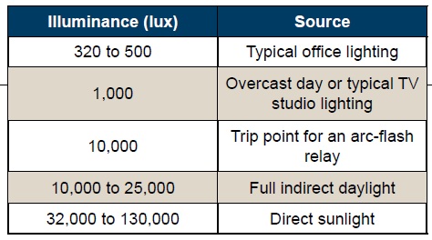
Some arc-flash relays also allow adjusting their light sensitivity, although most do not. Sensitivity is usually set at the factory at 10,000 lux. An arc emitting light below this level is not terribly dangerous. Nevertheless, it can be useful to raise the setpoint to help avoid nuisance tripping. For example, a worker welding nearby could inadvertently set off the relay, causing downtime and equipment damage if current transformers are not used.
The table provides some comparisons to different levels of lighting commonly found in the environment, which were taken into account in setting 10,000 lux as an arc-flash relay trip point. Even with current transformers, if an arc creates a flash of slightly less than 10,000 lux the system must rely on other protective devices to interrupt current flow to the arc, such as an overcurrent relay or fuse. A lightly overloaded fuse, for example, will interrupt current flow within about two seconds, about the time it would take nearby personnel to move off a safe distance. According to the IEEE 1584 Standard, an arc-flash of this intensity lasting for two seconds will expose nearby equipment and personnel to about 0.75 cal/cm2 of heat. This is not enough to create second-degree burns on human skin. The NFPA 70E Standard defines the threshold for its Risk Category 0 as 1.2 cal/cm2.
Arc-flash relay installation
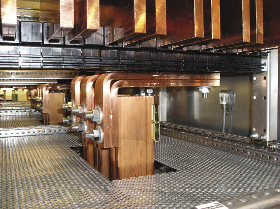
Arc-flash relays are installed in wind-turbine switchgear cabinets and switchgear at the base of the tower near bus bars in the control cabinet and the transformer. Most use multiple fixed-point light sensors near vertical and horizontal bus bars where arcing faults are more prone. Enough sensors should be installed to cover all maintenance areas, even if policy is to only work on deenergized systems. At least one sensor should have visibility to an arc fault if a person blocks another sensor’s field of view.
Light sensors may also be installed in other electrical cabinets and on panels that are subject to routine maintenance and repairs. In addition to fixed-point sensor inputs, at least one company (Littelfuse) also supplies fiber-optic sensors that have a 360° field of view for detecting light. This allows more flexible positioning of the light sensing locations, because fiber-optic strands can be looped throughout an enclosure or panel to cover challenging component layouts. One arc-flash rely, for example, the D1000 from Littlefuse, allows up to 24 light sensor inputs to comprehensively monitor any electrical equipment configuration. A USB port is also provided for setup from a remote PC, to access event logs (trips and the sensor inputs that caused them), and generate graphs of current data. WPE
Filed Under: Featured, O&M, Safety


Their products are well designed and manufactured using the best materials and techniques.
Find out more by shopping on the web at your leisure and in
order to compare and contrast the different prices. Human beings would have a
greater chance at a longer lifespan if the world’s air
and water were cleaner and free of chemicals.