To bring costs down, wind-energy firms are recognizing the design benefits of numerical simulation. Transitioning to a simulation-based design process lets OEMs optimize performance and increase a turbine’s power output.

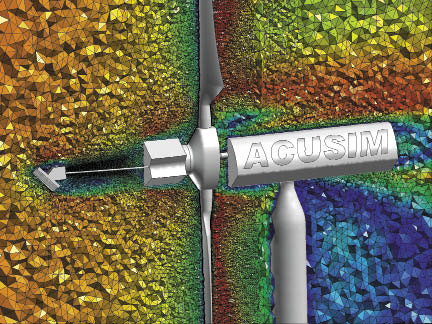
The turbine is an NREL Phase VI UAE design. An unstructured mesh can discretize the model without simplifying its relatively complex geometry.
A valuable tool in this process is Computational Fluid Dynamics (CFD) software. It has traditionally played a role in the design of rotorcraft, fixed-wing aircraft, and even wind-turbine blades. Previous limitations in computing power kept most simulations focused on small portions of a design with a limited inclusion of physical phenomena. Perhaps the most accepted use of CFD in the industry is for analysis of 2D airfoils.
Although an important application, recent advances in computing power and software provide greater capabilities for wind-turbine designers.
For example, multi-physics simulations are an important and emerging capability within computational fluid dynamics. Historically, CFD software focused on predicting fluid and thermal transport. Recent advances, however, now allow coupling or including additional physics into the simulation of the flow field. For instance, one technology with tremendous implication for wind-turbine design is Fluid-Structure Interaction (FSI). As turbine-blade designs become larger and use new materials, blade deflection under wind load becomes increasingly important.
Consider that in high wind, a blade could deflect to the point where it hits the tower. Turbine designers must also consider the change in the blade’s aerodynamic performance, and fatigue concerns can arise as a result of blade deflection. Engineering software providers such as ACUSIM enable engineers to efficiently and accurately simulate the behavior of rotating and deforming wind turbines.
ACUSIM’s finite-element based CFD solver, AcuSolve, contains two techniques for simulating such behavior in wind turbines. One technique uses Practical Fluid-Structure Interaction (P-FSI) technology for linear (small) structural deformations. This relies on a modal superposition approach to compute a structure’s deformed shape. The fluid loading on the blades provides excitation of the various modes of the structure, and the resulting deformation is the sum of each modal contribution. The approach is fast, reliable, and simple. All fluid and structural computations are performed by the CFD solver, so there is no run-time coupling of the solver to external codes. In the second technique, for nonlinear (larger) bending applications, the software supports run-time coupling to external structural dynamics codes using Directly Coupled Fluid-Structure Interaction methods. This lets users couple AcuSolve to a preferred structural solver, and requires no intervening middle ware to accomplish the coupling. The solver software handles the interpolation between dissimilar meshes (between the structural model and fluid model) and communication requirements. In addition, because the communication architecture relies on a standard socket connection between computers, structural and CFD codes can run on different compute resources using different operating systems.

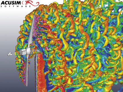
Iso-surfaces of Q criterion are ones that outline flow regions with local rotation, indicating a turbulent eddy. “Q” is a mathematical quantity commonly used to illustrate turbulent vortices in a flow field.
To demonstrate the FSI technology, we have simulated a fully coupled fluid-structure interaction on the NREL Phase VI UAE wind turbine. This design has a 10-m diameter rotor with two twisted and tapered blades. A fully unstructured mesh speeds model construction and solutions. The illustration An unstructured mesh shows the model mesh and complexity of the geometry, including the instrumentation hardware mounted on the front of the rotor. The software’s reliability, speed, and accuracy on unstructured meshes make it unnecessary to perform excessive geometric simplifications to the model.
The constant speed turbine was simulated at 72 rpm with a uniform inflow wind speed of 10 m/s. The Spalart-Allmaras based Delayed Detached Eddy Simulation turbulence model provides high resolution of the turbulent content in the rotor wake. The flexible blades were represented by a total of 20 structural modes using AcuSolve’s P-FSI technology. The blades were “softened” or made less stiff to make their flexing more visible, and to show that the solver can handle large structural displacements. The transient was simulated for six rotations in two-degree time steps. Undeformed and displaced blades is a picture at one time step and reveals the degree to which the blades respond to the wind loading.
Streamwise blade-tip displacement shows the time history as a function of the rotation. It highlights the unsteadiness in the simulation. The time varying displacement is induced by an unsteady turbulent loading on the blades, along with the blade and tower interaction as the rotor turns.
Numerical simulation using CFD will become increasingly important as designers pursue more advanced wind turbines. Combining unstructured meshing with an efficient CFD solver and multiphysics capabilities provides a powerful tool for designing wind turbines. Designers can use the software for standard aerodynamic simulations using rigid structures and the advanced capabilities of the solver for simulating complex phenomena such as active flow control and variable-pitch blades.
Filed Under: Software


Hi, I’m recently using CFD to simulate Phase VI turbine with a commercial software named SC/Tetra. Somehow the torque generation disobey the experiment, it goes down when the wind speed increase. However, when I took away the rotation, torque did increase with wind speed. I had checked geometry and analysis condition, no problem was found. I built another turbine using different airfoil and size, almost the same set-up. Then compared computational result with BEM theory and they match pretty much. Can you give me suggestion on what might be the problem? Thank you.