Despite the wide-spread use of three blade turbine, two blade versions offer fundamental advantages in light weight and low cost – if equipped with a teetering rotor.
 The 18th century Dutch built thousands of four-blade windmills, from Kinderdijk to Schiedam to Zaanse Schans. In the late 20th century, three-blade wind turbines became ubiquitous. Although several two-blade models have been developed, they have not yet gained the wide use of three-blade designs.
Two-blade rotors offer fundamental advantages in light weight and low cost—if they teeter stably. The rotor assembly of a mainstream three-blade wind turbine moves with one mechanical degree of freedom: it rotates. As blades turn and bend unequally due to turbulence, wind shear, and tower shadow, the resulting bending moments are reacted by the bearings and structure supporting the main shaft.
The power of two
The rotor assembly of a teetering two-blade wind turbine moves with two mechanical degrees of freedom: as it rotates, it teeters on a hinge between its hub and main shaft. Within engineered limits, this teetering can be mechanically free, eliminating bending fatigue loads through the main shaft due to turbulence, wind shear, and tower shadow. Eliminating these fatigue loads enables reduced weight throughout the main bearings, gear case, mainframe, yaw bearing and tower.
The power-to-weight ratios of ten modern wind turbines are compared in the accompanying chart, illustrating that teetering two-blade turbines are generally lighter than conventional three-blade designs.

The technician works in the pitch and teeter mechanism of a two-blade turbine.
While three-blade rotors require midair assembly, two-blade rotors can be assembled on the ground. The ability to install nacelle-rotor assemblies in a single lift reduces installation costs, particularly offshore.
To take advantage of free teetering, teeter amplitude must be kept within engineered limits, and high wind start-up and shut-down maneuvers must be carefully controlled. The first prototype turbine from New Zealand’s Windflow Technology Ltd was destroyed by inadequate shutdown control during an unusually strong wind shift in March, 2005.
To limit teeter activity, continuous operation in excessive wind shear must also be avoided. Wind farms in flat terrain are typically engineered assuming a wind shear exponent of 1/7, about 0.143. IEC design standards specify an assumption of 40% greater wind shear (α=0.2). Just as three-blade turbines must be beefed up to withstand the resulting fatigue loads, two-blade designs must accommodate the resulting teeter activity. The Windflow 500 design embodies a free teetering range of ±2.2°, beyond which a mechanical teeter-restraint system is engaged. The limit this places on tolerable wind shear is illustrated in plots, and is well above the IEC design value of 0.2.
Helicopter technology to the rescue
Many teetering two-blade turbines have been developed since the 1970s, but most have not achieved broad adoption. Tower shadow and strong wind shear cause damaging resonant forcing at rated wind speeds in any two-blader with a pitch mechanism not directly coupled to its teeter hinge. Pitch-teeter coupling is the essential feature which prevents damaging resonance.
Pitch-teeter coupling is well known in helicopter-rotor technology. In many helicopter rotors, each blade mounts on a “delta-3” hinge, which causes blades to feather as they flap in proportion to the tangent of the angle (delta-3) between a flapping hinge and a rotor axis. This coupling shifts the natural frequency of the blade flap away from resonance with the aerodynamic loads, stabilizing the resulting motion.
This natural frequency shift can also be achieved through a pitch linkage mechanism, which provides strong pitch-teeter coupling without need for a delta-3 hinge. Such a mechanism can offer advantages over the delta-3 hinge by maximizing the useful teeter range and the amount of pitch-teeter coupling within a given hub geometry.
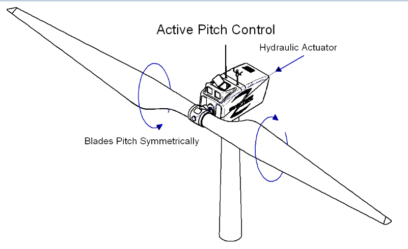
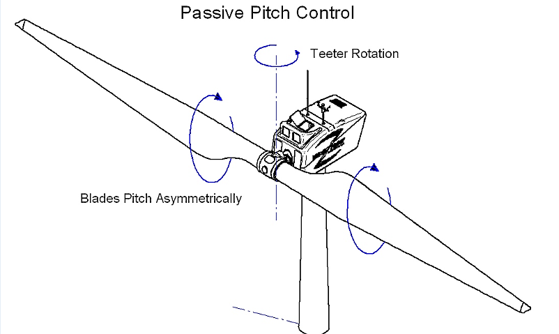
This type of mechanism is employed in the Windflow 500. The resulting pitch-teeter coupling induces passive, asymmetric pitching in response to teeter motion.
Inspired by the pitch-teeter coupled Wind Energy Group MS3 rotor developed in the 1980s, one two-blade turbine, the Windflow 500, has been refined into a design that embodies:
• A pitch mechanism with a coupling coefficient of about 1.5 (°pitch/°teeter)
• Rotor speed control logic fine-tuned to meet the requirements of every IEC load case
• A restraint system which can easily absorb the teeter impact of the maximum IEC load case
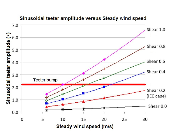
The plots show the wind-shear exponent versus Windflow 500’s teeter amplitudes. (Source: Windflow Technology Ltd)
Requirements for IEC certification
The response of the Windflow 500 to over 3,000 load cases prescribed in IEC WT 01 has been simulated with Garrad Hassan’s Bladed software. For example, to meet the requirements for generating in extreme turbulence (IEC WT 01 DLC 1.3), the turbine is designed to generate power in 16 m/s winds with >33% turbulence intensity. This load case provides the design-driving 560 kN·m bending load at the blade root. The design-driving ultimate teeter impact is predicted to occur during startup at 30 m/s during an extreme direction change (IEC WT 01 DLC 3.3, with a resulting yaw error of 37.5°). The bending strength of the mainshaft and gear case are driven by this requirement.
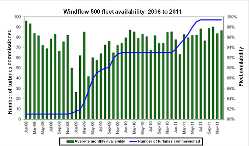
The chart reports the availability of one design of a two-blade turbine. (Source: Windflow Technology Ltd)
Strong pitch-teeter coupling provides the Windflow 500 with adequate stability to generate power in extreme turbulence, and to limit teeter excursions during high wind startups and shutdowns. While pitch-teeter coupling is a necessary ingredient, turbine durability is largely controlled by the detailed logic and software which controls the wind turbine, and which must be programmed to accommodate every possible scenario laid out in the applicable standards. Accordingly, to achieve this compliance, the PLC control system must be either connected or accurately represented throughout the thousands of simulations of turbine response required.
Independent Class 1A Type Certification to IEC WT-01:2001 (Edition 1) and IEC 61400-1:2005 (Edition 3) was awarded to the Windflow 500 in September 2010. Ninety-seven of the turbines are in commercial operation at the Te Rere Hau windfarm northeast of Wellington, New Zealand, where they have survived storms with gusts over 50 m/s while generating over 250,000 MWh and building the track record summarized in the chart.
Saved from extinction?
The familiar Dutch four-blade wind turbines of the 18th and 19th centuries were supplanted by three-blade designs during the 20th century. Threatened with extinction, the two-blade turbine has been nursed back to health in New Zealand. As wind farming moves offshore in the 21st century, look for a resurgence of two-blade turbines. WPE
By: John Arimond, Chief Technology Officer, Windflow Technology Ltd, Christchurch, New Zealand, www.windflow.co.nz
________________________________________________________________________________________________
Where have all the two-bladers gone?
By: Geoffrey M. Henderson, Founder & CEO, Windflow Technology Ltd, Christchurch, New Zealand
Teetering eliminates main shaft bending fatigue from turbulence, wind shear, and tower shadow. This fundamental advantage has been well recognized since the late 1970s, and has been exploited in many two-blader programs. Teetering two-blade turbines fall into five categories:
1. Stall-regulated fixed pitch turbines such as: ESI-54 (50 kW), ESI-80 (200 kW), Windane 12 (40 kW), AWT- 26 (275 kW), Carter (25, 175 and 300 kW), and Nordic 1 MW
2. Partial-span (tip) pitch-regulated turbines such as: Boeing 200 kW to 3.2 MW, Westinghouse 600 kW, Wind Energy Group MS1 (250 kW), and LS1 (3 MW)
3. Full-span pitch-regulated turbines with no pitch-teeter coupling, such as Hamilton Standard 4 MW, Maglarp 3 MW, Nasudden 2 MW and 3 MW, and Growian 3 MW
4. Full-span pitch-regulated turbines with pitch-teeter coupling by a delta-3 hinge such as Vergnet turbines
5. Full-span pitch-regulated turbines with pitch-teeter coupling by a pitch-change linkage such as: Wind Energy Group MS3 (300 kW), and the Windflow 500 (500 kW)
Few of these have been commercially proven because most failed to economically deliver sufficiently stable operation throughout a full range of wind conditions.
Teeter stability is a technically dense subject. In the early 1980’s, Dr. Andrew Garrad published several papers on the forced dynamic response of wind-turbine rotors. Garrad describes a teetering rotor with a natural frequency at 1/rev (neglecting damping). As wind shear and tower shadow give periodic teeter excitation at a driving frequency of 1/rev, the teetering motion of such a rotor is fundamentally resonant.
Garrad showed that a teetering rotor is fundamentally unstable unless its natural frequency can be shifted substantially away from 1/rev, or adequate damping can be maintained in all wind conditions. Turbines in the first three categories are prone to resonant teeter behavior. Those in the third category (full span, pitch-regulated turbines) remain damped and thus relatively stable in their teeter motion. But the first two categories lose significant amounts of aerodynamic damping when the fixed-pitch portion of the blade stalls, leading to damaging underdamped resonance in strong winds.
The addition of pitch-teeter coupling takes the system away from resonance altogether because it introduces aerodynamic stiffness as well as centrifugal stiffness, while also ensuring it does not lose the stability provided by aerodynamic damping.
Turbines in the fourth category provide pitch-teeter coupling by joining the hub to the mainshaft with a “delta-3” hinge. Many helicopter rotors mount each blade on a such a hinge, which provides pitch-flap coupling (flapping and teetering are analytically similar—flapping is less appropriate for wind turbines than helicopters because of the lower rotational speed and the greater importance of natural wind turbulence). Vergnet turbines (www.vergnet.com) reportedly incorporate such a mechanism.
Turbines in the fifth category provide pitch-teeter coupling through the kinematic design of the pitch change linkage within the hub. The Wind Energy Group MS3 turbine was the first to do this, obtaining advantages over a delta-3 hinge by maximizing the useful teeter range and the amount of pitch-teeter coupling within a given hub geometry. A number of MS3s have been in commercial operation in Cornwall, England for over 20 years.
As compared to the MS3, the Windflow 500 employs even stronger pitch-teeter coupling, pitching asymmetrically by about 1.5o for each 1o of teeter, as might hypothetically be provided by about a 60o delta-3 hinge. Such a delta-3 hinge could be impractical, however, as each 1o of blade teeter would result in about 2o of hub teeter, increasing the space requirements within the hub for the free-teeter and teeter-restraint systems, and creating design difficulties because of the proximity of the teeter bearings to the pitch bearings. The mechanisms in the MS3 and Windflow 500 offer a further advantage in that the pitch bearings experience an oscillating motion, whereas delta-3 hinges leave the pitch bearings stationary (when the collective pitch is stationary). This prevents false brinelling in the pitch bearing, so its life is determined by classic spalling fatigue, which is readily calculable for certification purposes. WPE
Filed Under: News, Turbines


Dear Sirs,
I would like to send on to your consideration several files containing the patent 27062 of Ukraine Rotor of Windmill.
I mean the following.
By use my invention there is possibility to enhance the productivity of the wind
farms by at least 15-20 % before they will achieve a rated power thanks to newly designed
blades. Each section of these blades has an additional impulse. The power coefficient Cp at this method is the nearest to the Betz’ limit. As known from blade theory the more the airflow deflection behind an airfoil section the more the driving force of wind turbine in whole. Leading edge slats installed at the roots of blades of horizontal – axis wind turbines allow to reach that. The additional impulses ensure to increase a number of rounds per time unit by wind turbine within speed-in and rated wind speed. After the rated power has been achieved, the rounds will be constant like at the prototype. For example, there is developed wind turbine with rated output power 100 kW at the appropriate wind speed of 13 m/s. Start up of this wind turbine is at 3 m/s. Straightening root area of blades (0-0 through X-X cross-sections), while the remainder zone is with its own relative twist angle. Install slats within named sections. What will we watch? First, start up of this turbine will be at lower wind speed compared to a prototype, at 2-2,5 m/s. Rated power of that wind turbine can be achieved already at the wind speed of 10 m/s, as it shown on
the applicable curve. This invention is working within named winds. That is enough I think, because not often the winds blow at which designed the prototype of wind turbine taken as example above.
This invention was filed on March, 1995 and published on February, 2000, bulletin 1.
Could you develop this project under agreement based on the technology containing in the patent 27062 of Ukraine Rotor of Windmill?
Respectfully,
Sergiy Kobka
Author
Proprietor of the patent #27062 of Ukraine “Rotor of Windmill”
Ukraine
97412
Evpatoria
Lenin Avenue, b.56, ap.132.
E-mail: sergiykobka@yandex.ua
P.S.It seems, for the large scale wind turbines we can cut off the 2nd section of the blade and remain the 1st one (with the slat only). I mean the blades with the relative tip-to-root twist angle of 70º through 90º in the initial phase of the prototype. What is it for? There is possibility to use the shorter towers and blades compared to a prototype at the same output characteristics, for example.