Inverter manufacturers need not settle for off-the-shelf enclosures that don’t sufficiently protect costly equipment. A collaborative design process between the enclosure and electronics manufacturers shows how it’s done in three steps.
Steven Leidig/Manager of enclosure engineering/Crenlo • www.crenlo.com/enclosures
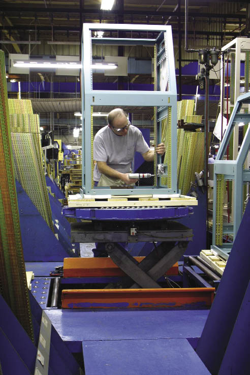
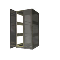
An assembly technician attaches a side brace on painted enclosure frame.
One of the most critical factors in the longevity of an inverter or wind turbine controller is its level of protection from harmful environmental factors, such as dust, corrosive agents, electromagnetic interference, temperature extremes, rain, snow, and more. To get the adequate level of protection against these factors, it is essential to select the right enclosure.
More often than not, these issues are best addressed by contracting a manufacturer to build a custom enclosure for the type of equipment being installed and the region in which it will be used. Many manufacturers view the process of commissioning a custom enclosure as a daunting, expensive, and time-consuming effort. With a better understanding of the process, however, this misconception can be rectified. Here’s an outline for a collaborative design process between enclosure manufacturer and electronics manufacturer in the development of a custom enclosure. In a nutshell, the process includes three phases: design, prototype and manufacturing.
Phase 1: Design
An inverter manufacturer in need of a custom enclosure to supplement its end product can engage an enclosure manufacturer in one of three ways —design the enclosure from scratch, work side-by-side in a joint development, or integrate an already designed enclosure into its manufacturing system. Let’s focus on the side-by-side development.
A collaborative design begins with a voice-of-customer analysis, consisting of a number of questions that will help kick off the design phase. For example:
What is the installation environment?
The reliability of electronics depends on their level of protection from harmful environmental factors such as dust, water, corrosive agents, ice, electromagnetic interference (EMI), shock and vibration, seismic activity, and more. What might be an excellent solution for an inverter in the Midwest may not be for the desert. Operating environment influences a number of design decisions, such as gasketing, materials, finishes, vents, filters, and more.
What is the total equipment weight the enclosure will carry?
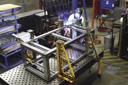
The Bluco table — soft tooling — allows building precise
enclosures in low volume. Hard tooling makes sense when quantities reach a particular figure.
Selection of nearly every enclosure component depends on a weight capacity —everything from casters, levelers, shelves and drawers, to sliders, frames, tie-down hardware, anti-tip bases and a slew of other components. Thus, weight is an essential piece of information to have in the beginning of the design process.
What industry regulations must be met?
With varying environments often come varying regulatory requirements. As such, enclosure manufacturers often must act as regulatory compliance consultants. These regulations are often based on installation environment. For instance, the International Building Code sets forth standards for how enclosures must be installed in areas with seismic concern. The National Electrical Manufacturers Association sets ratings for protection against environmental factors such as water and dust. The Federal Communications Commission has set forth guidelines for shielding against radio frequency interference, and the military has a wide array of standards that apply to specific installation scenarios.
What is the allowable operating temperature range?
Based on estimated ambient temperature range of the operating environment and waste heat generated from the equipment, the enclosure manufacturer can determine the appropriate size fan and conduct a pipe- flow analysis to ensure equipment stays within the allowable operating temperature range.
Once the voice of customer is complete, the enclosure manufacturer develops a 3D model of the design for review by the client’s engineering team.
How will the equipment be serviced?
The electronics manufacturer should be cognizant of the type of work that will go into regular maintenance of the equipment and ensure the enclosure is designed so that replaceable parts such as filters and fuses are easily accessible. The enclosure manufacturer can then conduct an ergonomic analysis to ensure that access panels are located in appropriate places. Additionally, safety considerations should be made such as grounding and the use of door locks to prevent open panels from swinging in the wind. If access control is a concern, exterior door locks can be installed as well.
What are target costs and quantities?
Lastly, it’s important to know the electronics manufacturer’s target costs, quantities, and frequencies of shipments to make final design and component sourcing decisions. Often, the enclosure manufacturer will make changes to the initial design to reduce costs without changing the enclosure’s fit, form, or function.
After all the necessary questions are answered, the enclosure manufacturer builds a 3D computer model, of which finite-element analysis is conducted to ensure structural integrity of the design. Once the design is approved by both parties, the process moves on to prototyping.
Phase 2: Prototyping
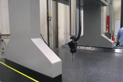
Inspection with CMMs, coordinate measuring machines, ensure the required precision has been met, a necessary step for seals and gaskets to work properly.
The prototyping process can take two paths — one built using soft tooling and fixturing and the other using full tooling and fixturing. The end result of both paths is a true representative sample — or first article — of what will be the mass-produced product. Tooling and fixturing come into play in two parts of production— pressing and welding.
Enclosures often have a number of components, such as doors and perforated side panels, that require a slew of bends, holes, and other features. These features are created by large press brakes. Without custom-made tooling for each component, an operator has to manually make each bend and hole in that component. However, tooling can be designed to create multiple bends or holes in one process, which can save the customer significantly on labor costs.
In the weld area, investment in fixturing means there is a structure custom-built to hold all pieces of the enclosure together while being welded. Not all enclosure manufacturers have an alternative that results in the same representative sample without investment in fixturing. Some do, however. Our company uses a platform called a Bluco table – a modular fixturing system. Essentially, the welder puts pieces together, much like an erector set, to replicate the fixturing system to the exact dimensions. The result is a welded enclosure identical to one welded using final fixturing. The only difference is that the welder has to set up and tear down the Bluco table before and after welding, which takes a bit longer, but does not require an up-front investment.
The decision to use soft tooling and fixturing or full tooling and fixturing is based on expected volume and cost. The investment in tooling means an up-front cost to the customer that must be justified. For instance, if tooling and fixturing costs $5,000 and saves $500 per unit in labor costs, then the volume should be a minimum of 10 to justify the up-front investment. If the volume will be 100 units, then it’s a no-brainer. However, the decision to invest in tooling must be made when there is a high level of confidence that there will be no major changes to the product that would render the tooling obsolete before it pays for itself.
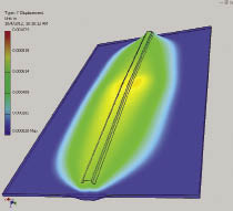
Finite-element analysis (FEA) is used in the design phase to judge the structural integrity of the proposed enclosure. Here, FEA is conducted on the door of the enclosure to pinpoint potential areas of distress based on the anticipated weight of the loaded enclosure.
Regardless of whether the customer chooses to invest in production tooling or not, various testing procedures are conducted to ensure quality and accuracy of every component that goes into the first article. Each component — whether fabricated or sourced — is subject to confirmation of dimensional accuracy (as compared to the approved 3D model) on a coordinate measuring machine (CMM). The results of every test on every component are documented for the customer’s records. This documentation is then provided to the customer’s quality and inspection team, and if approved, the documents become the gold standard for specifications of the eventually mass-produced enclosure.
Occasionally, based on unique customer needs, additional testing of the finished first article may be required. This could include something as simple as in-house weight load testing or water intrusion testing, to something more complex requiring testing at a certified third-party facility, such as shielding effectiveness from EMI in order to meet a specific military standard.
Phase 3: Manufacturing
Generally, after a first article is approved, production tooling will be created if it hasn’t been already. The exception to this rule would be in cases of low quantity custom enclosures that do not warrant the investment. Essentially, a mass-produced product would flow through the plant in the same way as its prototype. However, testing procedures would not be as thorough as testing each piece part on the CMM and documenting results. Rather, major structural features would be tested and marked as pass or fail throughout various stages of the process. This section will briefly outline the process of creating a finished enclosure from raw materials.
Most enclosures are made from cold-rolled steel or aluminum. These raw materials come in on large spools, which are then fed through a cut-to-length machine. The metal sheets are then stacked at an automated material server, which feeds the sheets into a laser cutter. This machine cuts out a number of different components for an enclosure, leaving little scrap behind.
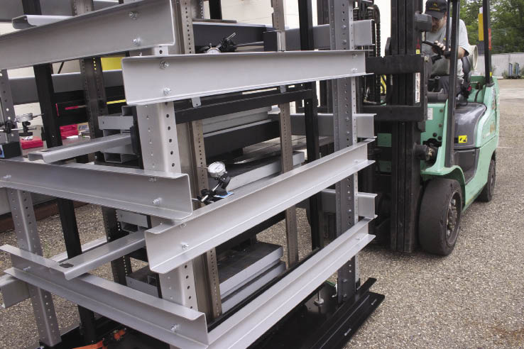
Enclosures are tested for their weight-load capacity by measuring deflection on several structural points of the frame when loaded with different static loads.
Each component will go through a series of bends on the press brake to form its shape. These pieces are then sent to the welding area, where they will be placed on the fixture and welded to form a portion of the enclosure. Each of these portions will flow through a powder paint booth and may be dipped in epoxy electrocoat, which provides additional corrosion protection for enclosures that require it. After drying, all the welded portions are assembled along with the bolt-on components, such as doors and side panels, that have also gone through paint. The enclosure is also outfitted with accessories requested by the customer, such as door locks, drawers, sliding chassis, fans, and vents. Once assembled, the custom enclosure is ready to ship.
Not so daunting
A misconception still exists among inverter manufacturers that commissioning a custom enclosure is time-consuming and expensive. Yet, by contracting an enclosure manufacturer with the flexibility to build a first article — a true representative sample of the production unit — without the commitment to invest in tooling and fixturing, the up-front costs are not as significant as one might think. Acting as an extension of the customer’s engineering team, many of today’s enclosure manufacturers work side-by-side in a joint development process that ensures the voice of the customer is understood, and the product meets all quality, functionality, aesthetic, and cost objectives upon development of the first article. From that point forward, the product becomes a standard unit, just like any of the off-the-shelf enclosures produced by the manufacturer. WPE
Filed Under: Featured, News