Sandia National Labs is a beehive of turbine activity. The last issue of this magazine reported on an array of test turbines going up in Texas and a concept 100m blade. Here we report on the Lab’s work on a possible 10 MW vertical-axis turbine and active blade-control surfaces.
Knocking on the 10-MW door

The vertical-axis turbine from the 1980s let Sandia engineers gather data that will guide the design of a larger unit over the coming months.
Although several 10 MW concept turbines are on drawing boards, they are mostly conventional horizontal axis-machine machines made larger and heavier. While their design teams labor along that route, a team at the Lab is working on a design idea that lost favor among large-unit OEMs – the vertical axis wind turbine (VAWT) or as they call it at Sandia, the “Vought”. The Lab’s project will span five years in two phases.
British firm Aerogenertor also says it is shaping a 10-MW VAWT, the Aerogenerator X, and it may partner with Sandia engineers. Risø-DTU in Denmark is also looking at a large Darrieus concept, a curved-blade design that resembles a large egg beater. To avoid duplication of effort, a loose cooperation among the three organizations will swap information to keep each abreast of the other.
For a horizontal axis wind turbine (HAWT) beyond the scale of 7 or 8 MW, the aerodynamic loads are no longer the turbine design drivers – it’s blade weight. What’s more, large HAWTs are difficult to point it into the wind, causing decreased performance. For example, large rotors are hit by different wind speeds and directions at different altitudes, so pointing the turbine becomes a compromise.
“Our study starts with a clean sheet of paper,” says Sandia Aerodynamics and Acoustics Lead Matthew Barone. “Phase 1 is to look at different rotor options and will narrow them down to something with promise, staring with the curved Darrieus design.”
One first task will be to develop analysis code to guide design work. In the late 1980s, the Lab built and ran a 34-m diameter Darrieus machine from which the Lab collected lots of data. This can validate aero-elastic design codes and then allow guiding new designs.

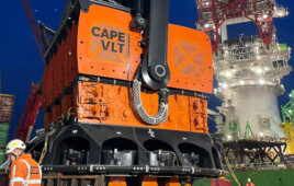
The selected blade is a standard Sandia CX100. The team decided to go with a modular construction so that future modifications could trade out motors and surfaces for other ideas. This iteration selected rigid flaps for relative simplicity.
Another Sandia engineer, Blade Reliability and Materials Lead Josh Paquette, will guide a team putting together a structural dynamics model for a general VAWT configuration, and validate it with the legacy data. Cost modeling will also progress in parallel with the analysis code to track the cost of energy that could come from a VAWT. The overall goal of the project is to demonstrate the feasibility of a large scale VAWT for offshore installations.
Several VAWT features make it a good candidate. For instance, the weight-induced fatigue issue of HAWTs is minimized and VAWTs don’t care about wind direction. A two-blade VAWT makes two sweeps through the wind, an upwind and downwind sweep. That generates some torque ripple, says Barone, because the torque increases and drops off with each rotation. But there is no gravitational cyclical load or buckling problem that HAWTs have as their blades sweep through the 12 o’clock position.
Three or four blades on a VAWT would smooth the torque. Helical blades are also a possibility. But more blades add cost.
The thrust bearing that supports the rotor presents challenges and may be a fundamental limitation of a VAWT. When scaling an on-shore design to multi MWs the bearings become enormous, and a challenge to manufacturing and reliability. So a floating design, similar to the Riso-DTU concept, would extend the tower into the water and use it to support the rotor weight. This idea gets rid of the one of the major limitations of the machine because it floats.

U.K. firm Aerogenerator X proposes this design to hit 10 MW.
At this time, a floating variant looks most encouraging. The U.S. has few good shallow-water resources but lots of deep-water regions. “The good thing about deep water is that it’s away from shore so there is no visual impact like that Cape Wind has dealt with,” says Paquette. “So to make offshore wind a player, think “deep water” to get to terawatt installations.”
The VAWT has a few problems to solve, such as resonances – a whirling mode or a precession at the top. The floating configuration provides a surrounding reservoir of braking or damping fluid that could mitigate the dynamic instabilities and resonances.
“Smart blade” heads to field tests
Rotor control is now mostly done with pitch adjustments. But as turbines are designed larger, it is a cumbersome method because pitch adjustments call for turning a large mass (the blade) and often within each rotation. A more efficient method would place active surfaces on each blade to react more quickly to varying wind conditions. Another thing is to tailor the aerodynamics to the inflow conditions. The idea is that if there are small disturbances, the rotor it could handle those as well. What’s more, such a design would react to changing wind speeds and directions common in the sweep of a large rotor. Proper pitch regulation also allows a smaller drive train because loads are not transmitted to the gearbox and generator.
Engineers at Sandia Nation Labs reported on a program that added active aerodynamic surfaces to a frequently used blade design, the 9-m long CX-100. Three blades were fitted with electric motors and controlling edge flaps. The test turbine is a modified Micon 65 with a 22-m hub height and now rated for 115 kW with a top rotor speed of 55 rpm. “The figures here are preliminary because we are in the middle of the tests,” said report presenter and Sandia engineer Jon Berg.

The test blade was fitted with several sensors, indicated by the squares on the blade. The strain (S) plots are for two of the sensors. U squares are accelerometer locations.
The control-edge flaps extend along 20% of the chord and along the blade’s outer 2m. They rotate 10° in either direction and with a frequency that can be increased. The blade includes sensors to measure its dynamic loads and eventually for better control. Modifications could include pressure taps and the capability of installing a pitot tube. Other sensors include fiber optic and strain gages to measure structural loads, and those for temperature. Accelerometers are at the maximum chord and the tip.
“The inertia of the flap is enough to excite a structural mode in the blade so it is possible to excite its resonance but the controller can eliminate that. Stepping through the frames of video from a camera on the blade shows we need to do more data processing to understand time delays. For example, in one frame we see flap movement and the next shows the blade responding to it,” says Berg.
The team is also conducting simulations for active aero dynamic load control and have shown a load reduction to peak and other fatigue structural loads, and a 5% reduction in cost of energy. “There are some uncertainties in the numbers because this is a first cut,” says Berg.
“For future work, we’ll analyze the data and compare it to simulations for dynamic damping, and find the time required by actuator response to refine the closed loop control,” he says.
Filed Under: Blades, Components, News


A brand new concept of a revolutionary turbine with self-adjustable blades has been introduced by Solatronic. Please takea look at http://www.solatronic.com/novak-turbine .
The specific webpages to study the involute spiraled vane VAWT are: http://www.fundamentalform.com/html/involute_wind_turbine.html and http://www.fundamentalform.com/html/wind_power_analysis.html
I have a unique involute spiral VAWT design that deserves extensive modeling and testing. It features non-constricting continuous vane involute spiral channels that divert the wind into the center, as a venturi turbine does, entraining outside air, rather than flinging it outward as a thin blade design does. Power is imparted by the wind as it travels through the total diameter of the spiral-vaned turbine, not just at thin blades, as in most other turbines. To learn more and see the promising prototype testing, go to my website: http://www.fundamentalform.com