The Gaia ultra-large wind turbine design solves today’s design and construction problems with existing components. The design also promises to drive down the cost of the power produced.
Rain Byars and William Miller
Nextwind, Inc.
St. Augustine, Fla.
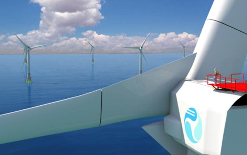
The wind-turbine architecture described here is a design concept which can be applied to wind turbines for rated outputs of 12 to 21 MW and higher.
The 5 to 8-MW range is the upper end of what can be achieved by enlarging current utility or MW-scale architecture. However, weights are high, the installation equipment is not commonly available, and the cost of energy is not on par with that available from 1 to 3MW onshore turbines. The question to address is: How can we upscale beyond this limit, and further push electric costs down? The Nextwind Gaia architecture overcomes the barriers to upsizing existing wind turbine technologies and aims to achieve large scale offshore wind plants beating the Initial Cost and Cost of Energy of land based wind farms.
The wind-turbine architecture described here is a design concept which can be applied to wind turbines for rated outputs of 12 to 21 MW and higher. This article presents a brief overview of the design goals and concepts with a focus on the drivetrain, the modular rotor system, and the offshore structure.
Design goals
In every turbine development, the designers must consider the driving design requirements which influence the return on investment, some main points being:
- Structural integrity and operational safety
- Up-front costs including materials, transportation, and installation
- Reliability
- Maintenance and service costs
- Annual energy production
For offshore installations and ultra-large wind turbines, Nextwind has defined the following additional goals which are considered critical to commercial viability:
- Reduce single crane lift weight
- Reduce single truck transport weight and dimensions
- Make every component field replaceable
- Reduce tooling investments and supplier non-recurring engineering
- Extend lifetime of entire structure
Architecture
The Gaia is an upwind, horizontal-axis offshore wind driven power plant with active control of yaw position, blade pitch, rotor rpm, structural loads, and power output. The design assembles like a bridge. The tower top structure is comprised of bolted standard shapes, and is intended to be assembled on site with a standard crane. Each drivetrain component can be repaired or replaced on site without dropping the rotor. Individual components then become replacement parts, instead of structural parts, and the structure can be maintained for an extended life.
Drivetrain
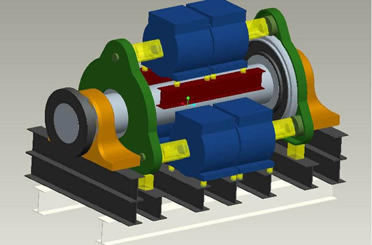
The Gaia Drivetrain comprises a long main shaft supported by two main bearings, two main gear assemblies, and six generators. The mainshaft is attached at the upwind side to the Modular Rotor System. The main bearings (upwind and downwind) can be removed from each end of the main shaft and can be serviced or replaced up tower.
Gear Assemblies
The main gear assemblies are supported on the main shaft between the two main bearings. The gear assemblies are segmented, and each segment can also be serviced or completely replaced up tower. The gear assemblies have a single-stage planetary configuration with multiple output shafts. This layout eliminates bearing wear associated with high-speed stages, and helps distribute and reduce tooth contact loads. The housings of the gear assemblies are supported on hydraulic dampers.
Generators
Each output shaft of the gear assemblies drives a permanent magnet generator. Dampers and torque limiting couplers are used to mitigate loads transferred between the mechanical and electrical systems. The generators are manufactured to a common frame size with minimal tooling investment required. The enormous size, weight, and loads on a conventional direct-drive generator with a 12-MW output would present challenges to manufacturing and transportation as well as reliable operation and field service. Medium speed generators have a higher power to weight ratio and use less rare earths and copper compared to a direct drive generator. The compact size and low weight allows low cost transportation and easy replacement in the field.
Structure
The entire drivetrain is mounted on a support frame made of standard forms bolted together. This eliminates costly tooling as well as manufacturing limitations and transportation restrictions associated with massive cast structures.
The support frame and drivetrain assembly are positioned into the current wind direction using an active yaw system. The load and position are controlled precisely with electric yaw drives and friction bearing.
Modular rotor system
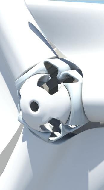
The Modular Rotor System comprises a central hub made of bolted shaped plate steel, structural blade support members, passive aerodynamic covers, active electric pitch system, and fiberglass blades.
The bolted hub concept eliminates costly tooling as well as manufacturing limitations and transportation restrictions often associated with massive cast structures. The hub assembly is made of standard materials readily sourced globally and transported by standard means.
Tomorrow’s rotor with today’s blade
Structural blade-support members and passive aerodynamic covers allow for a significant extension of the rotor area beyond what is currently possible with existing cast ductile iron hubs and fiberglass blade manufacturing technology. That means a 15 to 18-MW rotor is possible with blades currently in production for 6 to 8-MW wind turbines. Each structural blade support member is attached at an inboard end to one face of the central hub. The pitch interface is located at the outboard end of the structural blade support member. The blade mounts to the structural blade support with a bearing. An electric pitch drive changes the pitch position of the blade around the pitch axis.
The electric pitch system is adapted to the Modular Rotor System to withstand loads and environmental conditions at the extended pitch interface locations.
Offshore structure
Special challenges will come from a design for an offshore structure that copes with the strength and frequency requirements of large turbines. Neither conventional on-shore wind towers nor offshore structures for other purposes present a technology solution at this scale.
The proposed foundation system assembles from smaller components for ease of transport as well as on-site alignment and tuning. Therfore, the foundation assembly requires smaller cranes and support vessels compared to current 6 to 8-MW offshore foundations. The tower and foundation systems are designed to withstand higher loads, thereby increasing the estimated lifetime.
A transition piece between the underwater structure and the above water structure is designed to be self-aligning and forgiving of tolerance stack-up, installation accuracy, and settling.
Frequency tuning at installation
The stiffness and natural frequency of the offshore structure is limited by the operating (rotational) frequency of the wind turbine, as well as the periodic wind and wave loading. The natural frequency of the Gaia offshore structure can be adjusted and tuned at the time of installation by using inserts and variable masses. This allows achieving a precise theoretical natural frequency and adjusting it away from the theoretical values in case of factors not fully modeled during simulation, or change of operation strategy.
The overall weight and weight distribution can be adjusted with the addition of a cement-base section and variable ballast. Water, sand, or gravel could be used for a variable ballast.
The yaw interface and the tower bottom mounting interface could use optional spring elements to further fine tune the stiffness of the structure as well as allow some compliance.
Compliance
The tower should be able to withstand higher load by complying to extreme load events such as high winds or waves, or both. Compliance comes from achieved with local spring and damper elements sized to maintain stiffness during normal fatigue loads but deform under extreme loads.
Crush
For machine survival in extreme climate conditions such as a 100 year hurricane, the compliant elements could be designed as replaceable “crush zones”. Under extreme loads which might deform a structure designed with standard methods, the crush elements would yield, while the remaining structure remains intact. This crushed component would be replaced and the turbine returned to service.
Active frequency tuning
In soft-stiff wind towers, it is typical for the first mode tower natural frequency to fall within the operational rotational frequency of the wind turbine. Turbine control software monitors the operational frequency, and increases or decreases the turbine rotational speed to avoid the tower natural frequency.
With active frequency tuning, it becomes possible to change the stiffness of the offshore structure in real time during turbine operation to avoid high fatigue loads associated with a structure excited by turbine operation. The actuators are spring and damper elements located at the tower mounting interfaces capable of real-time adjustment.
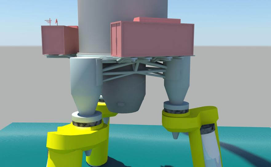
The foundation assembly could use any of several different spring elements, such as Bellville springs, rubber disks, and other designs already in use by the oil and gas industry
Final thoughts
The Gaia represents a shift in design philosophy, which is necessary to overcome existing barriers. Various subsets of the Gaia architecture can be applied separately to different wind turbine designs. When all parts of the Gaia architecture are implemented together, the Gaia becomes a true wind-driven power plant.
Initial studies indicate that the initial cost per MW of the Gaia is competitive with on-shore turbines, but beyond that, the real advantage is seen in the reduced transportation, installation, and service costs which push the offshore cost-of-energy below current on-shore levels.
Filed Under: Construction, Offshore wind, Turbines

