A few ideas for enhancing power outputs might let vertical axis wind turbines exceed the Betz limit without violating it.
Editor’s note: Posting this article is not a endorsement of the methods expressed in it. This is just an exchange of ideas.
Peter Allen Sharp, sharpencil@sbcglobal.net
It is no longer true that the main advantage of VAWT is that they do not need to orient to the wind. Now their main advantages are that they can capture more wind energy, or capture wind energy more cheaply, or both, than is possible for HAWT — by using some of the following techniques:
1) Use an extremely wide VAWT (a low rotor-aspect-ratio) so that most of the wind passing through the upwind blade pass has time to speed up to close to the wind speed before reaching the downwind blade pass. The VAWT can be composed of a very large ring riding on wheels supported by towers, with the wheels mounted on the shafts of elevated generators. The blades would be mounted on the ring. [1] [2] For added rigidity, use two rings, one above the other, with the blades and bracing between them. Mounting the blades on a large ring would minimize aerodynamic drag.
Typically, the upwind VAWT blades capture 80% of the energy, and the downwind blades capture only 20%.
If we assume that, for an extremely wide VAWT, the downwind blades could capture 75% of what the upwind blades capture, then the VAWT would capture 80%, plus 75% of 80%, which is 60%, for a total of 140% as much energy as a square-shaped VAWT would capture. If the square VAWT had a coefficient of power (Cp) of 0.45, then the extremely wide VAWT would have a Cp of 0.63, which is beyond the Betz limit for HAWT (0.593). (Actually, the Cp could be still higher because the solidity ratio and torque could be increased without lowering the tip speed ratio, due to reduced back pressure.)
Clearly, when computing the Betz limit for VAWT, the aspect ratio of the rotor must be taken into account. Wider VAWT are more efficient. [3]
2) Tip the VAWT toward or away from the wind to increase the swept area and the power. Wind tunnel experiments at Delft University achieved a 35% increase in power by tipping a VAWT 25° toward the wind. [4] A much wider VAWT should show a larger increase in power at a smaller tipping angle.
Tipping can also be used to deflect the wake at a rising or falling angle to increase mixing with the wind, while directing turbulence away from turbines located downwind. [5]
3) Place counter-rotating VAWT close together in a row, perpendicular to the wind, to cause the wind to accelerate through the gaps between the turbines, which can reduce turbulence and increase the air flow through the turbines. A computer simulation by Mehrpooya at Purdue University (Master’s Thesis, 2014) found that two turbines spaced 1.5 turbine diameters apart (from shaft-to-shaft) achieve a 22% increase in power when the tip speed ratio is 3. [6] Presumably, gaps on both sides of a turbine should double that increase.
N. H. Thomas mentions that Bob Thomas measured a 75% increase in power for a long row of his fixed-blade VAWT (Wind Harvest International). [7] This technique is called “turbine coupling” or the “vortex coupling effect”. Bob Thomas patented the technique in 2002. [8]
However, in a 2012 grant report for a computer simulation, given to the California Energy Commission, Wind Harvest International stated that the middle rotor of 3 rotors, with a Cp of 0.43, increases its Cp to 0.49 by using turbine coupling — an increase of 14%. The increase for the end rotors was not discussed, but would probably be about half that increase, or 7%. The spacing between rotors was minimal. Larger spacing was not discussed. Their prediction is based on using rotors with a low solidity ratio and a tip speed ratio of 3. [9]
4) Use an especially tall and slender turbine so that it can spin faster than a conventional 3-bladed HAWT with the same swept area, and can therefore use a smaller and less expensive direct-drive-alternator. If the VAWT consists of stacked, infinitely-variable-pitch, cycloturbine rotors, they can adjust to the differences in the wind speed due to the wind gradient and to their different tip speed ratios from the top to the bottom of the stack. Also, the rotors in the stack could have different solidity ratios so as to keep them at their optimum tip speed ratios.
5) Use a simple, low-cost, passive, cycloturbine with passive, independent-blade pitching and infinitely-variable-pitch, to capture more energy from wind gusts, and thereby capture more kilowatt hours per year, than is possible for fixed-blade VAWT. An optimized fixed-blade VAWT can achieve a high Cp, but the power curve is peaked. An optimized cycloturbine can achieve a slightly higher peak power, but the biggest difference is that the power curve is much broader, meaning that the cycloturbine is much more efficient at lower tip speed ratios. That increase in annual energy capture could be expressed as equivalent to an increase in a cycloturbine’s Cp. Blade pitching can increase the energy capture by 20% to 35%, as determined by different researchers. [10] [11] [12]
Accurate cycloturbines also produce less turbulence than fixed-blade VAWT because the cycloturbine blades do not experience dynamic stall.
At present, the Sharp Cycloturbine (patent expired) seems to be the best choice because it is simple and cheap to build, it should have a high efficiency (the Cp should be about 0.45 because the pitch control functions like an analog computer), and it should be especially good at capturing the energy in wind gusts because each blade responds instantly and independently to changes in the velocity of the wind.
It uses a passive, infinitely-variable pitch-schedule for each blade, which closely approximates the ideal pitch schedule for a cycloturbine VAWT at all tip speed ratios (TSR) above 1. The blades do not stall — except during start-up when stall is used to increase the starting torque. It should have strong starting torque, a broad power curve with peak torque at a TSR of about 2, and it should operate at a TSR of 3 to 3.5 when the solidity ratio is about 0.17.
It can use straight blades, V-blades, or curved blades. V-blades can withstand high centrifugal force. The pitch-control system costs almost nothing and has nothing to wear out (because there is no “control mechanism”, just the wind and centrifugal force acting on the blade). The blade bearings can be just cords that twist. [13]
If computer-controlled-motor pitching for individual cycloturbine blades can become cheaper, simpler, and more durable, it may become the best choice for medium-scale and large-scale cycloturbine VAWT because they could exceed a Cp of 0.50. [14] [15] [16] [17] [18] Their control mechanisms mean that they probably would still be too expensive to compete with the Sharp Cycloturbine at the small-scale.
6) Because some of the above techniques can reduce turbulence, they allow for closer spacing of VAWT on wind farms. Closer spacing would allow a wind farm to capture more energy per square meter of land than HAWT. It should also lower the height of the turbines and achieve a greater vertical planform energy flux, meaning that more energy can be extracted from the wind above the turbines to replace the energy captured by the turbines. Prof. John Dabiri, now at Stanford University, is the leading researcher in this field. [19]
HAWT on a wind farm are typically arranged relative to the direction of the strongest winds. They are spaced about 5 diameters apart across the wind, and about 10 diameters apart extending downwind. Pairs of counter-rotating VAWT can be spaced about 4 to 6 diameters apart in both directions because they reduce turbulence.
7) Arrays of VAWT could be mounted in a frame that oriented to the wind. The purpose of doing so would be to create a large swept area without the usual corresponding volume and weight of a single, large wind turbine. The frame structure becomes an essentially two-dimensional structure that would be much lighter and less expensive than a single wind turbine with the same swept area. In other words, a wall of framed VAWT would benefit from the square-cube law of scaling. The wall could also benefit from turbine coupling and turbine tipping.
New Designs
The sketch showing an array of “Sharp VAWT Coupled Turbines” illustrates how to make use of turbine coupling for stacked rotors with 2 blades each. The suspended array orients to the wind and also swings away from the wind for overspeed control. Both techniques cost almost nothing.
An alternative configuration: The individual rotors in each stack could be modified to be about 4 times as wide as tall (rotor aspect ratio of 0.25), and spaced apart vertically, so that when the array swung (tipped) about 10 degrees away from the wind due to wind pressure, the downwind blades would be exposed to clean air. That would increase the swept area and the power of the rotors another 35% or more. That is equivalent to raising the Cp by 35% or more.
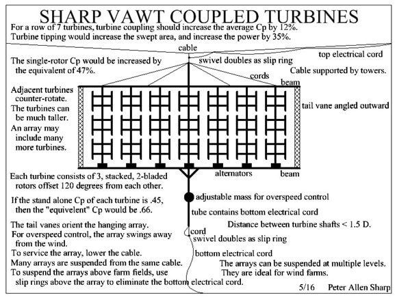
So if the turbines had a Cp of 0.45 when vertical, and turbine coupling raised the Cp to 60% on average, tipping would have the same effect as increasing the average Cp to about .80. (Note that none of these techniques violate the Betz limit.) The most efficient large-scale HAWT at present has a Cp of about 0.51. So a Sharp Cycloturbine array could be almost 60% more efficient than a single HAWT with the same total swept area. And the array could also be much less expensive.
If the suspended VAWT array were used on a wind farm, by using arrays as if they were individual wind turbines, and arranged in horizontal rows, with vertical stacking of the rows, and vertical spaces between the rows, the gain would be even larger and might more than double the amount of energy captured annually as compared to a HAWT wind farm. That is because the arrays could be arranged with closer spacing between them due to their lower turbulence and their greater ability to benefit from the vertical planform energy flux.
The turbines in each suspended array could be much taller, and/or many more could be used in a row. The array as shown could be lightened by eliminating the adjustable weight and using a horizontal pivot axis above the center of gravity of the array. All of the rotors in a row could be linked mechanically so that only one generator, or one air compressor for air storage, would be needed per array. When more than one array was suspended from a cable, each array should have its own lowering cord and electrical cords so that it could be lowered separately.
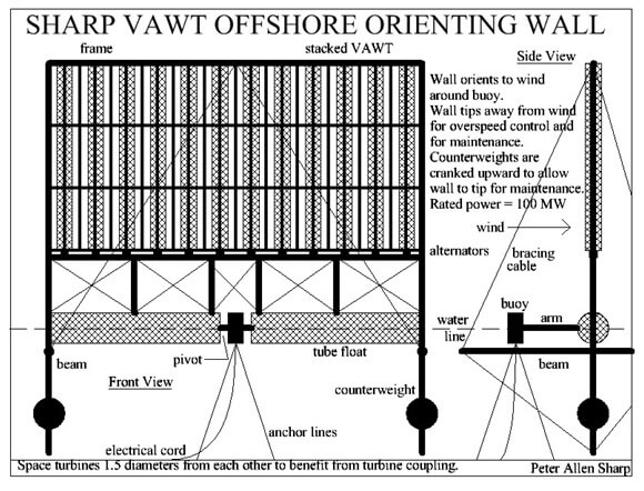
Sharp Cycloturbine arrays over water (Wind Wall, see sketch) could be made extremely large (100 MW) by using the water to create a floating yaw bearing. Floating arrays could also include wide VAWT with spacing between the VAWT in a stack to increase the efficiency of the individual VAWT when tipping.
It is not yet clear whether it would be cheaper to stack the rotors close to each other vertically or to space them apart vertically to take advantage of tipping. Using turbine coupling, but with no gain from turbine tipping, the Cp would be about 0.51. If turbine tipping were added, the equivalent Cp would be 0.66, but the vertical spacing of rotors would lower the total power output.
This off-shore array could be further improved by using floats mounted upwind and downwind of the main frame. The stability of the frame would then be similar to that of a trimaran. The upwind float could be partially flooded to provide ballast and additional resistance to tipping. For maintenance, the upwind float would be emptied of water and the downwind float would be flooded. Along with raising the “keel” weight, that would make it possible to easily tip the frame to horizontal. An additional float could be added to the top of the frame to provide buoyancy when the frame was horizontal.
As seen from the side, the floating array is like a two–dimensional structure as compared to a 3-dimensional, single, gigantic VAWT (or HAWT) with the same swept area (which is not possible using current materials). That achieves a large cost saving. The principle utilized is the square/cube law of scaling. An essentially two-dimensional structure will weigh much less than a three-dimensional structure with the same frontal area, and weight is closely correlated with cost. By using hollow designs, conventional, large-scale windmills do not increase their weight by the cube, but by an exponent of 2.3 to 2.4. However, that is still significantly more than an exponent of 2.
Using many smaller VAWT rather than one big VAWT or HAWT means that the parts could be mass produced and shipped in standard containers, thus further lowering the costs. If the cost of wind energy is substantially lowered, that makes wind energy viable in areas with lower wind speeds, thus greatly expanding the market and further lowering the costs of mass production, which in turn makes even lower average winds worth capturing. (This is the virtuous circle effect.)
Arrays of VAWT spaced close to each other would make it feasible to connect them mechanically or hydraulically so that they could all drive a single generator, pump, compressor, or fluid friction heater. Wind Wall arrays might also be used for water desalination, or for storing compressed air in bags anchored at great depth [20] (and saving the heat of compression so as to inject it back into the compressed air when generating electricity [21]).
It is possible to construct a single VAWT that can take advantage of both turbine tipping and turbine coupling. The technique is to fold the VAWT so that its sections are in a row, and then couple the section to each other and to a direct-drive alternator.
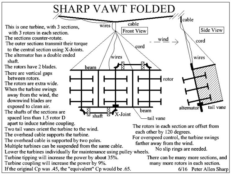
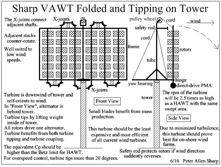
These folded Sharp VAWT uses “X-Joints” to connect the folded sections (stacks) to each other. It is a gearless, low-tech, low cost, right-angle joint that I invented. These single VAWT would have an “equivalent” Cp (based on the upright swept area, without folding) that was significantly higher than is even possible for a HAWT.
These new types of VAWT wall-arrays that orient to the wind should be able to produce electricity for a much lower cost than is possible for HAWT. If they can, then VAWT will replace HAWT for most applications. So the next time you admire a huge and elegant HAWT, consider that you may be looking toward the past, not the future, of wind power.
—————————————————————————————————-
References and notes
[1] Lyatkher, Victor M., Wind Power, 2013
Or search for “Lyatkher wind power Fig. 5.2”
See Fig. 5.3. It shows a VAWT consisting of a very large ring with blades on the ring and the ring resting on multiple towers with generators, 1987; a very low-aspect-ratio rotor.
[2] Young, Richard Nils, March 15, 2012, patent
http://www.google.com/patents/US20120061972
For extremely wide VAWT with blades on ring, and the ring riding on wheels driving generators, with the generators on towers around the ring. (If smaller, could be placed on hillside to take advantage of skewed airflow up the hill.
[3] Brusca, S., Lanzafame, R., and Messina, M.
“Design of a vertical-axis wind turbine: how the aspect ratio affects the turbine’s performance”
Int J Energy Environ Eng (2014) 5:333–340 DOI 10.1007/s40095-014-0129-x, 20 Aug. 2014
Shows that VAWT that are much wider than tall are more efficient. See Fig. 4 and 5.
[4] Mertens, Sander; van Kuik, Gijs; and van Bussel, Gerard
“Performance of an H-Darrieus in the Skewed Flow on a Roof”, 2003
Delft University Wind Energy Research Institute, Faculty of Civil Engineering and Geosciences, Stevinweg 1, 2628 CN Delft
See Fig. 12. Tipping the model 25 degrees resulted in a 35% increase in power.
If the VAWT were much wider, this increase should be larger, at a smaller skew angle.
[5] Chowdhury, Abdullah Mobin
“CFD analysis of tilted vertical axis wind turbine for offshore application”
Master’s Thesis, June 2014, Sonargaon University, Bangladesh.
In the Conclusions, point #5, he mentions that the wake of a VAWT tilted rearward is angled downward, so a following VAWT may not experience as much wake turbulence as usual. If a Sharp Cycloturbine tips toward the wind, it will angle the wake upwards where it will be swept away more easily.
[6] Mehrpooya, Payam, “Improvement of vertical-axis wind turbine performance via turbine coupling”
Master’s Thesis, 2014, Illinois Institute of Technology,
Why turbine coupling (same as the coupled vortex effect) increases efficiency. He found that a spacing of 1.5 D was best at a TSR of 3. It gave a 22% increase in power for one pair of counter-rotating VAWT, with their retreating blades adjacent. That is 22% per turbine, on average. Coupled vortexes gradually cancel each other.
His study did not address what the turbulence does in the vertical direction. Presumably, a gap on both sides of a turbine would increase the power 44%.
[7] Thomas, N. H., online discussion group, no date.
http://www.navitron.org.uk/forum/index.php?topic=14602.20;wap2
Claims that the Wind Harvest International’s VAWT achieves a Cp of .495. Claims that extended measurements by Bob Thomas showed that a row of counter-rotating VAWT with a gap of less than 1 radius between them can capture 75% more energy when the row is perpendicular to the prevailing wind.
http://www.windharvest.com/our-history/ The history of Wind Harvest International and the “coupled vortex effect”.
I have not found any papers by Prof. Ion Paraschivoiu on the “coupled vortex effect”.
[8] Thomas, Robert Nason, patent on the coupled vortex effect.
https://patents.google.com/patent/US6784566B2/en?q=coupled&q=vortex&q=effect
The patent covers only paired, stationary wind turbines in the claims, but long rows of VAWT are mentioned in the text and shown in the drawings. There is no mention of rows of closely spaced VAWT that orient to the wind. So the designs in this article appear to be not-obvious, original, superior, and patentable.
[9] Thomas, Robert and Wolf, Kevin; Wind Harvest International
“Modeling Blade Pitch and Solidities in Straight Bladed VAWTs”
Final Report, Feb. 12, 2012, Energy Innovations Small Grant Program, California Energy Commission, Grant #: 08-03. (Thanks to Kevin Wolf for this paper.)
———
This quote is placed above Fig. 55, page 83:
“Analysis at TSR=3
For TSR = 3, simulations for 1 and 3 original distances between rotors indicate the same Cp of 0.49. For 1 rotor, the Cp is 0.43. Clearly, in this case the vortex effect is stronger as seen in Figure 56.”
There is no Fig. 56 in this report. See Fig. 55, which shows a substantial increase of torque for the two downwind quadrants of the middle rotor of three rotors when the row is perpendicular to the wind. There is no data presented for the 2 end rotors. The increase in Cp from 0.43 to 0.49 is due to turbine coupling using close spacing (blade paths are 0.16 radius apart), a low solidity ratio (16.5%), and a TSR of 3. That is an increase of power of 14% for a rotor with rotors on both sides of it. The end turbines should experience an increase as well, so I will assume a 7% increase in power for end-of-row rotors. That implies that the average power increase will be larger for a longer row of turbines. Example: A row of 7 rotors should show an average increase in power of 12% per rotor. Blade tip plates are predicted to increase rotor power by another 6%. Fairings for the support arms should be NACA0025 for minimum drag. Much larger gaps (1 rotor radius between blade paths) were not discussed.
Assume that an array of 3 rotors facing the wind would increase its average power by 9.33% per rotor due to turbine coupling. Assume that a single rotor (Sharp Cycloturbine) has a Cp of 0.45. Tipping increases the power by 35%. The total increase in power is 44.33%. So the equivalent Cp is 0.649.
Assume an array of 7 rotors facing the wind would increase its power by 12% due to turbine coupling, and 35% due to turbine tipping, for a total increase of 47% per rotor. If the upright, single-rotor Cp was 0.45, then the equivalent Cp would be 0.66, which is well beyond the Betz limit for HAWT. Blade tip plates should increase the equivalent Cp by 6% of 0.45, which is 0.027, so the final equivalent Cp becomes 0.70.
[10] Erickson, D. W., Wallace, J. J., and Peraire, J.
“Performance Characterization of Cyclic Blade Pitch Variation on a Vertical Axis Wind Turbine”, 2011, Massachusetts Institute of Technology Department of Aeronautics and Astronautics, Cambridge 02139
http://enu.kz/repository/2011/AIAA-2011-638.pdf
Blade pitching can increase efficiency of a VAWT 35% over fixed blades. See his Conclusions.
[11] Benedict, Moble, University of Maryland, video, Sept. 39, 2012
https://www.youtube.com/watch?v=EqLL2uj33mg
Shows a four bar linkage pitch control for a VAWT. See graph indicating that a cycloturbine VAWT could have a very high efficiency. His cycloidal system pitches the upwind and downwind blades to the same degree, which is less efficient than an infinitely-variable pitch-control for each blade separately.
[12] Rathi, Dhruv
“Performance Prediction and Dynamic Model Analysis of Vertical Axis Wind Turbine Blades with Aerodynamically Varied Blade Pitch”
A thesis submitted to the Graduate Faculty of North Carolina State University in partial fulfilment of the requirements for the Degree of Master of Science Aerospace Engineering Raleigh, North Carolina 2012
http://repository.lib.ncsu.edu/ir/bitstream/1840.16/8079/1/etd.pdf
See his Fig. 5.1, pg. 78, for the power curve of a VAWT with optimum pitch control so as to maximize torque, as compared to a fixed-blade VAWT. The Cp is higher when torque is maximized than when the lift-to-drag ratio is optimized.
[13] Sharp Cycloturbine, videos and photos
It is not a Darrieus rotor; it is simpler, cheaper, and more efficient.
https://www.youtube.com/watch?v=LXUiDx-F6FI&feature=youtu.be Model A1 for students; cantilevered rotor; flat, paper V-blades, lighting LED.
https://www.youtube.com/watch?v=QssKlt3kHmY Model F1; rotor in frame.
https://www.youtube.com/watch?v=JfFMuWId358 Model blade test by Jeff Doyle; single blade lifts weight to demonstrate strong torque. Blade bends outward due to centrifugal force to create a Sharp centrifugal-pendulum-spring blade for pitch control.
http://www.youtube.com/watch?v=nSidUyvbmZI C-blade model Sharp Cycloturbine by Jeff Doyle.
http://www.getlinkyoutube.com/watch?v=_o4OZhXFsb4 Straight blade model Sharp Cycloturbine by Jeff Doyle.
http://www.flickr.com/photos/69351046@N08/6299256860/ Photo: Straight blade Sharp Cycloturbines: 3’ diameter and 4’ diameter models.
http://www.flickr.com/photos/69351046@N08/6298724205/ Photo: Model land yacht driven by Sharp Cycloturbine; starts and sails directly upwind and in circles.
I have technical papers explaining how the Sharp Cycloturbine works. The Sharp Cycloturbine has not yet been formally tested and analyzed because engineers typically assume it is too simple to pitch accurately, even though they don’t understand it. It is much more sophisticated than it looks. Attempts to analyze it using simplifying assumptions, such as ignoring inertia, lead to erroneous conclusions.
[14] Anderson, J. W., Brulle, R. V., Birchfield, E. B.
“McDonnel 40 KW Giromill Wind System; Phase I – Design and Analysis; Volume I – Executive Summary” August 1979
http://wind.nrel.gov/public/library/3032execsum.pdf
See Fig. 5 showing a Cp of about .50. This was a constant rpm cycloturbine, so the blades pitched hardly at all in a 12 mph wind speed because the TSR was over 5. At 60 mph wind speed, the TSR was about 1.3, so the blades had to pitch a lot. Note that the power required for the actuators was only 0.6 kW for all three. Each actuator included a motor, gearbox, toothed belt drive, and a computer. The output was 53 kW aerodynamically, but only 45 KW for the final electrical output due to various drag-inducing design flaws. The motors were unreliable. This cycloturbine should have been used to continue to study and improve pitch control; not doing so delayed VAWT research by decades.
[15] Morgan, W. A. (McDonnell Aircraft Giromill study)
“Giromill Wind Tunnel Test and Analysis; Volume I – Executive Summary”, 1977
http://wind.nrel.gov/public/library/gwt.pdf
They measured two different wind speeds in the wind tunnel using two different measuring devices. They predicted that a large Giromill 60 feet in diameter with 30 foot blades should have a Cp of .54, based on their wind tunnel data.
[16] Inerjy, company website
http://www.inerjy.com/island-power/Vertical-Axis-Wind-Turbine-Plans-Build-In-New-Technology.html
Claims that their computer controlled, pitching-blade VAWT are capable of a Cp of 51.5. They give no details of the system, and show no power curves. Their biggest VAWT is 250 kW, and their other VAWT is 55 kW.
[17] Miau, J. J. (1), Liang, S. Y. (2), Yu, R. M. (3), Hu, C. C. (4), Leu, T. S. (5), Cheng J. C. (6), and Chen, J. C. (7)
“Design and Test of a Vertical-Axis Wind Turbine with Pitch Control”
Applied Mechanics and Materials Vol. 225 (2012) pp 338-343 Online available since 2012/Nov/29 at www.scientific.net © (2012) Trans Tech Publications, Switzerland doi:10.4028/www.scientific.net/AMM.225.338
1,2,3,5National Cheng Kung University, Taiwan
4Kao Yuan University, Taiwan
6National Formosa University, Taiwan 7Temple University, USA
http://www.iaa.ncku.edu.tw/~aeromems/Publication/2012_VAWT%20pitch%20control.pdf
See Fig. 7. VAWT Pitch control can achieve a Cp of .56, and greatly improved performance at low tip speed ratios as compared to a fixed-blade VAWT.
[18] ZHANG Lixun(张立勋), LIANG Yingbin(梁迎彬), LIU Xiaohong(刘小红), GUO Jian(郭健)
“Effect of blade pitch angle on aerodynamic performance of straightbladed vertical axis wind turbine”
- Cent. South Univ. (2014) 21: 1417−1427 DOI: 10.1007/s1177101420807 College of Mechanical and Electrical Engineering, Harbin Engineering University, Harbin 150001, China © Central South University Press and SpringerVerlag Berlin Heidelberg 2014
http://static.elitesecurity.org/uploads/2/2/2260965/cikloidni_opt.pdf
See Fig. 14; shows optimal pitch schedule compared to cycloid pitch schedule, for a TSR of 2.2, which gives about 20% higher output for the optimal pitch schedule. The Sharp Cycloturbine can closely approximate the optimal pitch schedule, so it should be about 10% to 20% more efficient than cycloidal pitching (and cost much less).
[19]Dabiri, John, video, 11/15, Stanford University
https://www.youtube.com/watch?v=pAGAcGoyP8Q
Discussion of experimental wind farm using counter-rotating paired-VAWT.
[20] Cummins, Kate
“Compressed air energy storage has bags of potential”
The Engineer, 25 April 2011
Compressed air stored in inflatable bags deep in sea, anchored to sea floor.
[21] http://www.lightsail.com/
Lightsail Energy. Compressed air storage in tanks; the compressor becomes the air motor. During compression water is sprayed into the cylinders to save the heat of compression. That warmed water is injected into the cylinder during expansion to regain the heat of compression. The process can be over 75% efficient.
Filed Under: News, Turbines