By Kyle Smith, principal application engineer, The Timken Company

Wind turbine gearboxes designed to last two decades are showing damage often within five to 10 years, leading owners and operators to seek stronger solutions.
The evolution of wind turbine gearbox design has resulted in the use of an increased number of tapered roller bearings throughout the parallel shaft section to effectively manage both the radial and axial loads produced by helical gearing during operation. This arrangement includes a cylindrical roller bearing in the float position coupled with a two-row tapered roller bearing in the fixed position, typically in a direct-mount configuration (also referred to as a face-to-face, DF or X arrangement). Compared to conventional arrangements that commonly use various cylindrical, spherical, ball and thrust roller bearing configurations, this stronger approach can better support varying loads experienced during gearbox operation, helping wind farm owners and operators avoid costly repairs and downtime.
For service technicians and rebuilders, this trend toward two-row tapered roller bearings requires that close attention is paid to controlling the assembly’s associated mounted setting. Unlike many conventional bearing types, two-row tapered roller bearing designs are composed of separable components with an unlimited range of axial locations relative to one another based on the installation method used.
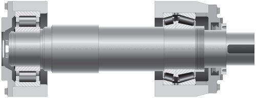
A floating cylindrical roller bearing (left) paired with a fixed two-row tapered roller bearing (right) is becoming the preferred method for managing loading conditions seen in wind turbine gearboxes.
These separable components require an external means of controlling the final relative axial location and resulting mounted setting, which is most commonly done by introducing a component spacer into the assembly. This spacer is then specifically machined to a controlled width by the installer or by the bearing supplier during the assembly production. However, many MRO professionals with limited tapered roller bearing experience have questions about how to achieve the best mounted setting results. And without proper mounted setting control, the resulting stresses can become excessive or may even result in unloaded conditions inside the bearing, leading to roller and cage damage.
This article reviews three common approaches for obtaining a final axial setting for a two-row tapered roller bearing assembly using a controlled spacer width.
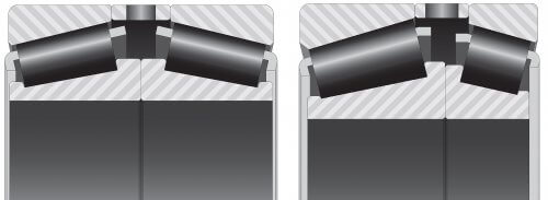
Roller angles, among other variables, can be customized, allowing two-row tapered roller bearings to better handle combined loads compared to traditional cylindrical, spherical and ball bearing designs.
Green spacer assemblies
A green (or unground) spacer assembly is intentionally supplied with a spacer that has extra width to allow the user to tailor various settings based on specific application requirements. Note that in some instances, bearings may be supplied without a spacer (typically when the user intends to produce or purchase one separately), in which case the combination of bearing components and spacer would be treated similarly when obtaining the target nominal mounted setting. Two common methods of obtaining the target mounted setting for a green spacer assembly are the measurement-and-calculation method and the manual push-pull method.
Measurement-and-calculation method
The measurement-and-calculation method requires the user to obtain measurements of the shaft, housing, bearing bore and bearing outside diameter (O.D.) to determine the actual mating component fitting practice. Secondly, the user must obtain the correct lateral loss factor(s) for the bearing assembly part number to support an accurate lateral loss calculation due to any resulting interference fits. Finally, the spacer gap between the bearing components at zero bench setting must be calculated using assembly component physical measurements (also known as drop measurements) or measurements obtained from the bearing supplier, thus allowing the user to determine the final spacer width to reach the target nominal mounted setting.
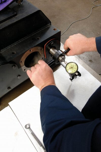
The manual push-pull method measures total shaft axial movement using a dial indicator.
Push-pull method
Alternatively, the manual push-pull method requires the user to mount the bearing components and the unground spacer using the actual mating shaft and housing components to determine a baseline mounted setting value. This baseline setting can then be compared to the target nominal mounted setting to determine the spacer width that must be ground to achieve the target setting.
The push-pull method requires all rollers to be seated completely and uniformly against the adjacent large rib and requires that no external components or loads interfere with the ability to obtain an accurate measurement of the axial shaft movement in both the push and pull steps of the process. To ensure that rollers are seated and an accurate axial setting is measured, an axial load must be applied to the shaft in one direction while the shaft is oscillated a minimum of 20 times before applying an axial load to the shaft in the opposite direction while oscillating the shaft as before. The total axial movement of the shaft is the bearing assembly mounted setting.
Assuming proper procedures, a green spacer makes it possible to achieve an optimal final mounted setting, given that the actual dimensions from the mating bearing components, shaft and housing are accounted for, thus eliminating (most) tolerances from the equation and resulting in a very small possible mounted setting range. However, inaccurate measurements, incorrect calculations, imprecise spacer grinding, mismatched mating components or the inability to obtain an accurate push-pull measurement due to component size or adjacent component interference will directly impact the ability to achieve a high level of precision and consistency, leading to an unpredictable possible mounted setting range that can lead to a range of problems.
Matched spacer assemblies
A matched spacer assembly (also referred to as a single bench setting assembly) is supplied with a fixed width spacer that has been ground by the bearing supplier to a specific width based on an assumed set of component fitting practice values and a target nominal mounted setting value for the application.
For this type of assembly, the bearing production facility completes the bearing physical measurements to understand the spacer gap between components at zero bench setting and to determine the final spacer width necessary to reach the specified nominal mounted setting. Both the assumed fitting practice range and the calculated lateral loss would be considered by the bearing supplier to determine the bench setting for the matched bearing assembly.
A matched spacer could be considered the least accurate approach to obtaining a target nominal mounted setting given that the shaft, housing, bearing bore and bearing O.D. tolerances all have a direct effect on the possible final mounted setting and are not accounted for on an individual combination of mating components, thus resulting in a relatively large possible mounted setting range.
Bore-compensated spacer assemblies
A bore-compensated assembly (also referred to as a variable bench setting assembly) is supplied with a fixed-width spacer that has been preground to a specific width based on an assumed set of component-fitting practice values and a target nominal mounted setting for the application.
To begin, the bearing supplier again completes drop measurements to determine the spacer gap between the components at zero bench setting and final spacer width to reach the target nominal mounted setting. The difference between this assembly type and a matched spacer, however, is that the potential interference fit range between the shaft and inner ring bore is broken down into multiple groups, such that a different bench setting value can be selected based on the actual component bore dimension (rather than using a single bench setting for the entire interference fit range). This results in a more tightly controlled selection of the final spacer width and a reduced target mounted setting range.
Typically, the target mounted setting and shaft tolerance are obtained from the user or from application engineering review. Engineering then performs calculations that cover the known inner ring fitting practice range to develop a table of bench setting values. This table allows the bearing supplier to select a single bench setting based on the actual bearing bore measurement and associated shaft tolerance combination. The bearing supplier then completes the measurement process to understand the dimension of the spacer gap at zero bench setting to thus determine the final spacer width necessary to achieve the target nominal mounted setting.
Bore-compensated assemblies are considered more accurate than matched assemblies, given that the bore tolerance variable and associated lateral loss are already accounted for in the fitting practice; however, this method cannot achieve the extreme accuracy of a properly controlled and processed green spacer assembly.
Note that this assembly type typically assumes a loose fit or a very light interference fit between the bearing outer ring and housing. In other cases, special compensation matrices may be necessary to accommodate interference fits at both the bore and O.D. of the bearing assembly.
The following table can help you understand the relative advantages of different assembly types (on a four-point scale, one star is acceptable and four starss is optimal):

Avoid these costly mistakes
Bearings that use a spacer to control the final mounted setting may be unfamiliar to many service techs. Keep the following advice in mind when maintaining or upgrading gearboxes:
- Do not use an old spacer in a new bearing assembly.
- Do not swap spacers between old and new assemblies.
- Do not install an assembly without a spacer unless another axial setting mechanism is present (e.g., spring-loaded system or component end-cap).
- Never install a green spacer that has not been ground to proper width.
- Never assume a supplied spacer is the correct finished width.
- Always take time to measure and verify.
Where to turn
It is wise to consult a qualified expert to review the described measurement, calculation and assembly procedures when installing bearings that rely on a finished spacer width to control the mounted setting. Your trusted adviser can provide the support and clarity needed to ensure a successful outcome that avoids major corrective work. As the use of two-row tapered roller bearing assemblies in wind turbine gearboxes becomes more prevalent, it is only a matter of time until such questions arise. Be sure to ask your bearing supplier about training and education that can put your team ahead of the curve.
 Kyle Smith is a principal application engineer for The Timken Company with a current focus on wind gearbox applications solutions and upgrades. He is based out of the company’s world headquarters in North Canton, Ohio. Kyle has held past engineering roles in support of various industrial markets, including power transmission equipment, aggregate and crushing equipment, paper production equipment and heavy moveable structures. He has been with Timken for 14 years. Kyle earned an associate degree in mechanical engineering technology from Stark State College and a bachelor’s degree in manufacturing engineering technology from the University of Akron.
Filed Under: Bearings, Components, Featured, Gearboxes


Very nice. I think it is difficult to discuss MEP without actual numbers. And the listing of costly mistakes to avoid is a real keeper. Will there be a ’round 2′ with an actual example of MEP with all the methods listed? Good job. Nice tie, too!
I like this article. It’s concise and it summarizes the advantages and requirements of the various features and configurations that contribute to obtaining the correct setting in a difficult environment. Nice going Kyle.