
Paul Bundy
Paul Bundy / Energy Service Manager / AIMCO
There is significant debate in the bolting industry as to how to best measure torque. When using electric torque drivers, one camp suggests that monitoring electric current provides sufficient torque control. A more recent position suggests that a torque sensor in the head of the tool works better. To understand the difference and importance, one must understand the accuracy difference between transducerized (a sensor in the output shaft) and current-controlled tooling.
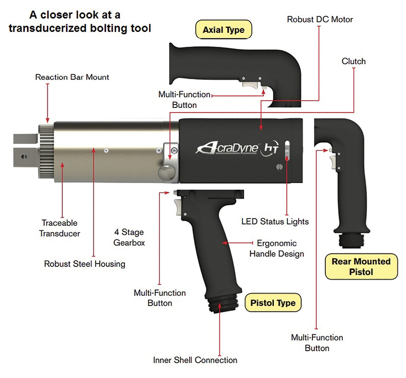
A transducer torque control system, such as this AcraDyne design, provides consistent, reliable torque values as well as a method for monitoring rotational angles when tightening bolts. This unit can be up to three times faster than competitive tools.
Current controlled (Open loop): Bolting tools are dedicated systems consisting of a tool, cable, and controller. They are pre-calibrated in a lab using an external transducer on a rundown fixture. The tool is operated on the external transducer at set torque points. The amount of current supplied by the system is matched to the torque reading of the external transducer. The lab will input these torque readings which the system translates into the amount of current it must supply to produce a required amount of torque.
Unfortunately, current-controlled tooling is an “open loop” design. Once the tool is removed from the external transducer, there is no torque feed back in the system. It simply supplies the pre-set current and the operator has to assume the torque was properly applied.
However, several parameters affect the torque output but not the torque readings of the system. Things such as temperature, gear wear, voltage, and motor performance all effect torque output. But the system is unable to adapt and compensate for these changes. It’s all guess work. It’s also a dedicated system, so something as simple as changing out the cable voids the calibration.
Transducer controlled (Closed loop): Tools such as AcraDyne’s HT system, have a transducer built into the output shaft of the tool. The transducer is constantly measuring torque in real time and feeding data back into the system. Variations of temperature, gear-ware, voltage and motor performance do not affect the accuracy of the transducerized system because they all happen before the transducer. The system will simply keep applying power until the transducer reads the requested torque before shutting off. Such a system also records date, time, and rundown information for up to 32 different preset torque jobs stored in the controller. All recorded torque data is easily exported into an Excel file with the touch of a finger. Unlike current controlled systems, the modular design provides a dedicated system. The calibration of a transducerized tool is done to the tool not the system. Tools, cables, and controllers are all interchangeable. When the annual calibration is due, users need only send in the tool, not the whole system.
When users expect accurately applied torque, remove the guess work and use a closed loop transducerized system for much better accuracy.
Filed Under: Featured, News