This is the unedited transcript for webinar: Cost Benefit Analysis and Argument in Favor of Replacement of Mechanical Turbine Control Wind Sensors. Click here to watch the webinar on demand.
Paul:
Well, hello everyone. Thank you for joining us for today’s webinar, Cost Benefit Analysis and an Argument in Favor of Replacing Mechanical Turbine Control Wind Sensors. Before we begin, I’d like to cover a few housekeeping items. At the bottom of your audience console you’ll see several application widgets for your use. For instance, when a question or topic arises during the webcast click on the Q&A widget and type any question there. I’d encourage you to ask questions, and don’t wait until the end of the presentation either. Submit your questions as they occur to you, and we’ll try to answer as many of them before our time is up. Should a question deserve a fuller answer or we run out of time, it will be answered by email. We capture all the questions.
A copy of today’s single deck webinar and additional materials are available in the Resource List widget that looks like a green folder at the bottom of the screen. You can expand your slide area by clicking on the maximize icon at the top right side area or by dragging the bottom right corner. If you have technical difficulty, please click on the Help widget, the one with the question mark. An On Demand version of the webcast should be available tomorrow and can be accessed using the same audio link that was sent you earlier. Today’s web cast is presented using a slide deck and not a screen share or live demo. If you want a copy of today’s presentation, click on the green Resource List widget at the bottom of your audience console and download from the documents listed there.
If you don’t see the slide movement on your console, hit the refresh icon in your browser URL bar or hit F5. Now, let me tell you a little bit about our speaker. In fact, we have sort of a guest question answerer today as well. Our guest speaker is Abraham Aguilar. Mr. Aguilar is the Director of Business Development at Lufft USA. He has a background in industrial automation dating back 8 years. His technical experience coupled with his role as Weather Sales Director for Lufft, a manufacturer of weather sensors, has made him an expert in Turbine control anemometery.
His role at Lufft is to continue the companies market focus in developing it’s market research in the Canadian, USA, and Latin America markets. Abraham’s responsibilities include business growth, partner acquisition, project management, technical support, and marketing. Then, during the question and answer period, Abraham will be joined by Tristan Lee who has worked on swapping mechanical wind instruments with ultrasonic versions. Mr. Lee is employed in the United States strategic business unit of the AES Corporation. He’s a veteran performance engineer with an extensive background spanning nearly a decade in modern wind turbine design operation and project development of Vestas, GE, Seimens, and Mitsubishi Turbines. That’s quite a lot. He’s been heavily involved and led various studies revolving around wind turbine meteorological systems having published several white papers on his findings along with patent pending algorithms related to the wind distortion induced in a post rotor wind vigilance system. Let’s see and that’s enough for me. How about if we get rolling. Okay Abraham. I think the microphone is yours.
Abraham:
Paul, thank you very much for the opportunity and thank everyone for joining us today. A special thanks to Tristan Lee in joining us in our Q&A session, as well. Before we start, I wanted to give everyone an introduction as to who Lufft is and where we come from.
Lufft was actually started by Gotthilf Lufft, founded the company back in 1881 in Stuttgart, Germany. In 1989, a group of investors, kind-of, took over the company and redesigned the company to become more of a digital focused company. The gentleman in the middle of the picture is Klaus Hirzel. He is the CEO and Managing Director of Lufft, currently managing our entire business unit for the company. The gentlemen to the left of him is Axel Schmitz-Hubsch, which is our senior engineer and the main designer of a lot of the products that we currently sell at Lufft.
Presently, I wanted to let you know a little bit more as to where we have come from in the last 130 years of doing business. We are now part of the Danaher group, which is a 20 billion dollar organization. We’re ranging everything in the globe when it comes to weather information systems, as well as, industrial components. As far as where we are in regards to the world, Fellbach is the headquarters for Lufft. We are based close to Frankfort, in the middle between Frankfort and Munich. We also have some series in the United States, as well as, in China. I, myself, am based out of the L.A. branch or the Santa Barbara office, which is in the southern coast of California.
In 1903, Lufft became market leader in metal barometer business sector. Presently, we are now involved in a wide array of industries and markets ranging from industrial devices for laboratories, as well as, cabinet control sensors or transportation sensors for datalogging capabilities. We also have a market segment in traffic, where we are focusing on RWIS, which is road weather information systems, with a lot of the Department of Transportation divisions within the United States and the Americas. We also have a mobile weather sensor that’s able to capture a real-time weather on a consistent basis and provide that information to the cloud for real-time monitoring. But, for today, we want to focus on the business sector that we cover in regards to wind and weather. Primarily, our biggest focus has been in the renewal energy, including solar and wind. I also cover meteorological, hydrological, and building automation opportunities.
For the last couple of years, I’ve been able to go to different types of conferences and workshops where I meet with and interact with a lot of operations maintenance companies. Pretty much the feedback in the industry has been that they’re looking for a way to reduce cost and increase production overall. They’ve informed me that there is a lot of icing issues that cause production loss with the current sensors that are mounted on their turbines. They want a simple to use and simple to implement solution that would solve a lot of the problems that they’re currently seeing. They did inform me, as well, that they are having a lot of mechanical sensor issues, where they require replacement or that the sensors need yearly recalibration because of their mechanical components that are caused by wear and tear, so they need recalibration every year. They also informed me that they need a low cost, robust sensor, because this is definitely going to impact their bottom line. Of course, the sensor needs to meet regulatory requirements to be able to be installed.
The sensor that we provide at Lufft is the Ventus. It’s primarily designed for wind turbine applications. It comes with a factory certificate. Every sensor that we manufacture comes with a factory certificate. There really is no need for recalibration, because there is no moving part within the sensor. It’s an ultrasonic sensor, so there is no mechanical components to it. The sensor has a dual heater, that prevent icing from forming and also prevents rimming. The dual heaters … There’s a heater on the top of the sensor on the plate there and then there are heaters embedded within the ultrasonic sensors to prevent any ice from accumulating. The sensor by itself has both digital and analog outputs, so that helps with the simple integration of any wind turbine currently in operation.
We did our research and we actually meet or exceed the NRC Regulatory Guide of 1.3 requirements, which is wind direction of plus or minus 2 degrees and wind speed of plus or minus .45 miles per hour. This sensor has gone through Halt testing, meaning that our MTBF at 20 degrees Celsius is 22 years. We have an MTBF of 22 years or so. The corrosion test that we’ve provided has past and we also have done a vibration testing on this sensor. There’s also been an icing testing, as you can see in the picture. It’s a picture of the icing testing that we did, where ice accumulated around the sensor but no ice or ice particulate actually accumulated within the sensor head. The sensor is an IP66 sensor.
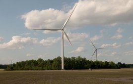
For this analysis, we’re going to go over three different types of sensors. We’re going to talk about Ultrasonic Ventus, which like I mentioned before has no moving parts, includes a temperature control for icing events, has a lifespan of this analysis … We did a lifespan of 5 years, which I mentioned we have a MTBF of 22 years. We understand there is a higher upfront cost compared to the other items or other sensors that we’re going to be covering, but we are also understanding that within the higher cost we will be able to explain why the higher cost would be beneficial in the long term or the lifespan of the wind turbine. The sensor does provide wind speed and wind direction, but it also provides for other controls like being able to measure the signal quality of the wind speed and wind direction. There’s a channel within the sensor, you can read that. As well as, has a virtual temperature sensor, where looking at the wind speed or as the particles of the air go through the sensor, you are able to kind-of capture a virtual temperature. That is a channel within the sensor, as well. Like I mentioned before, this has a digital, as well as, analog output protocol directly from the sensor.
The cup anemometer … This is an example of a cup anemometer that currently in the market space. This could be or may not be exactly the same thing that you might have in your current wind turbines, but it’s something similar to what’s out in the market space. As you can see, it has a lot of mechanical parts, which are subject to weathering. Of course, the weight and the inertia of the moving cups may negatively impact the accuracy of the reading. We understand that systems like these have a low power requirement and they’re inexpensive, at least in the upfront cost. There is a mechanical failure rate as high as 1 per year and that’s something that we calculated within the analysis as part of the assumptions and may have a frequency to be recalibrated on a yearly basis. Similar to the cup anemometer, the vane anemometer has the same type of mechanical failure points. There’s also a portion where some of these vane anemometers require a signal conditioning, as well as, additional wiring, which we’ve captured within this analysis.
Other assumptions that we did for this analysis that we conducted interviews. Within those interviews, we were informed that about 40% of all mechanical sensors needed annual replacement due to failure. We did our research and we found that an average wind turbine technician makes about $23.46 cents per hour. This is added into our labor cost. There was a 5 hour maintenance time to repair or replace mechanical sensor. This 5 hours is for the labor cost of getting a technician out to the site and repair or replace the mechanical sensor. Like I mentioned before, signal conditioning, as well as, additional wiring are additional costs for mechanical units in some situations. Industry reports that icing occurs about 5 times per year. We assume that if a farm has 100 turbines, then the probability of icing occurring is about 5%. The information gathered informed us that about $40 an hour is lost in production when a mechanical sensor is down. We also assume that it would take about 2 weeks for the sensor to be repaired on the field, so we took that into the analysis.
When we calculated the numbers, we did a cumulative cost of the total of owning one of the mechanical sensor versus owning an ultrasonic sensor. As you can see here, the total cost of owning a mechanical sensor that is non-heated is $1,819 compared to the Ventus, which is $2112. If you look at the graph, we actually show that we could have a return on investment within the first year. Now, if you look at the total overall cost within 5 years. Again, the assumption is that both sensors are being compared in a 5 year timeline. The cumulative cost of owning a mechanical non-heated anemometer is about $4730, and this cost is with the assumption that it’s going to be a 40% replacement need due to failure that occurs within the mechanical anemometer.
This is how we calculated the $1,819 for the mechanical sensor. We took the base price of the mechanical sensor, added the shipping cost of $50. The labor cost, like a mentioned before, is $23.46 per technician per hour at 5 hours. The cost of failure is $40, which is the cost per hour of lost production times 5 hours to repair times 40% annual replacement due to failure. For this particular situation, we added in the signal conditioning requirements that would be needed for a mechanical sensor and the additional wiring costs that are required for the mechanical sensors to operate. We also incorporated the cost due to icing which is 40% of production lost times 24 hours times 14 days until replacement is placed and the probability of icing of 5%. That accumulated to $1819.
Someone may say, in my case, I don’t have any signal conditioning or additional wiring cost, so what would the cost look like. In that case, if we took away the signal conditioning and wiring cost, the total cost of owning a mechanical sensor is $1219, as you see here illustrated. What does this do to our graph? It actually shows that return on investment, if no signal conditioning or wiring costs are included, the return on investment for owning a mechanical sensor compared to a ultrasonic is a three year return on investment, as you can see clearly on the graph.
How do we calculate the cost of the Ventus ultrasonic anemometer. The cost of $2112 was looking at the base price of $1945 for the base price of the Ventus. There’s a shipping cost of $50 that we assumed. $23.46 for the technician times 5 hours to go up and replace the sensor. Because we are not expecting to see any failure from the ultrasonic or any signal conditioning, wiring cost or costs due to icing that would be eliminated within the total accumulation of the total cost of owning an ultrasonic sensor.
We did also an analysis on identifying what the cost would be if we owned a mechanical heated anemometer and the cost for this is actually higher compared to an ultrasonic sensor, where the cost of an anemometer that’s heated is about $900. When we looked into each individual item, it came out to $2419 compared to the ultrasonic that’s only $2112. If we looked at the cost and removing the cost of icing or removing the cost of additional wiring, as well as, signal conditioning, you can see that the cost of the mechanical heated anemometer drops significantly to $1147. However, the return on investment over the lifespan of the sensor could be within 3 years, as you can see here illustrated in the graph. After a certain amount of time, the accumulation of failures just keeps on increasing the cost of ownership of a mechanical heated anemometer.
This graph shows if we were to incorporate the cost of icing in the mechanical heated anemometer. The reason for this is because we’ve heard within the market space that even though they’re owning heated anemometers there tends to be icing formation and causing of failure points within the sensors. If we took into account the cost of icing due to production loss, the cost actually comes out to about the same as if you didn’t have a heated … if both the heated and the non-heated were incorporated. The cost comes out to $1819. Again, the return on investment could be simply within a year of purchases compared to the ultrasonic anemometer.
What we really wanted to highlight in this slide is that if you take into account icing. Icing is a really big cost adder in the regards to the ownership of mechanical sensors. As you can see here in the first section or the first column, this is a column illustrating mechanical sensors that are non-heated. The total cost within a 5 year timeline of owning a non-heated mechanical anemometer is 53% of the cost due to icing. For the second column, we didn’t illustrate icing because we said, if the mechanical sensor is heated you won’t have that additional cost. But, as you can tell because of the failure points that tend to occur, it’s definitely more expensive or double the cost compared to an ultrasonic. Of course, with the mechanical, with communication protocol, you would remove the cost of signal conditioning or additional wiring, but there’s still the cost of about 48% due to icing that occurs. Again, these other costs are not incorporated within the ultrasonic because there are not signal conditioning or icing issues that could occur.
When we did the analysis over a 20 year timeline, it really highlights and illustrates why using an ultrasonic sensor would be the most ideal way to reduce costs and increase production. This table shows the 5 year costs of the anemometer using at 100 turbine wind farm installation. We’re kind-of estimating that that is the size of a wind turbine farm. At 5 years, the cost of owning anemometer is $211,230, which equates to the cost of a single anemometer times 100 turbines. When we did this correlation across all the other ones, you could tell that the lifespan of owning a heated mechanical anemometer or a non-heated mechanical anemometer is double or almost twice the cost of owning ultrasonic. We recommend going with the ultrasonic anemometer just because of the cost savings that you could incur by going with one of our sensors.
Don’t take our word for it, primarily. We’ve worked with other ONMs. Currently, like I mentioned, on the call, we also have a representative from AES. AES has incorporated our product offering for their wind turbines in replacing a lot of the mechanical anemometers to our Ventus platform. Terra-Gen is another ONM company that we’ve worked with that is also doing the same. We also have OEMs like WEG and Goldwind who are using our Ventus and have standardized on our product offering because they also see the benefit of using our technology.
What we are asking for you is to look at your current wind farm and identify where our potential technology would be most ideal for your installations. We understand that there is about 48,000 installations out there and we feel that there’s a need for our technology to be incorporated within the American Wind Energy Department or industry. I did want to give you a heads up that I will be at the OWIA show on May 25 from 4:30 to 6pm during the poster session. We’re going to be having a poster describing and talking about just this analysis and the data points that we did to get the data points that we have and presented to you today.
In summary, let us help you save in operation cost and increase production. Like I mentioned today, you could have a return on investment on your sensor within 1 to 3 years. I have provided my contact information should you have any questions or any concerns in regards to the numbers I presented to you today. Paul …
Paul:
My phone …
Abraham:
Paul, are you there?
Paul:
Okay, there. Can you here me?
Abraham:
Now we can here you Paul.
Looks like we’re having some technical difficulties with Paul. If at this time, I think we have some questions. I’ll help Paul out here a little to see if we could address some of these questions.
One of the questions that I have here was, what’s your assumption that mechanical sensors are replaced annually?
From our history and from talking to a lot of the owner operators, we were told that replacements are occurring about 40% of the time. There needs to be a replacement at least in 40% of the time when they are installing the mechanical anemometers. Another thing is that they’re replacing them because they need be recalibrated on a yearly basis.
Tristan, are you there?
Tristan:
Yes.
Abraham:
Go ahead and chime in.
Tristan:
I’ll elaborate a little bit on that. What we found with the mechanical sensors are over time as the bearings stand rolling resistance, they tend to be reluctant to spin as fast as they should for a specific wind speed. What that actually does is it creates a condition where the cups aren’t able to accelerate or decelerate at the same rate as the calibrated sensor. At that point, the turbine controller is no longer able to calculate a correct turbulence intensity, which is extremely critical in terms of how fast the turbine needs to spin its rotor and how much energy is actually being felt actually through the drive train, main bearing and namely the planet stage. A lot of people won’t notice this because it actually starts making the turbine look more efficient because it’s actually under inflating the perceived wind speed. The basis of changing them yearly is so that the turbines aren’t operating in that type of condition, which is extremely fatiguing on drive train.
But, if you go by the Ice Free 3 anemometers from NRG. They recommend every 2 years minimum replacing it. The KK sensors, it’s every few years. It depends on the type of sensor and also the operating environment. If you have a lot of thunderstorms or extremely aggressive wind shear, they’re more susceptible to acceleration during shear conditions or turbulence. If that helps.
Abraham:
I appreciate that. Paul, are you able to come back on? Can you hear us? I think we lost Paul. Any other questions from the webinar?
Stacy:
Hey Abraham, this is Stacy. I think we lost Paul. His phone doesn’t sound like it’s working at the moment. You do have another question that came in. It says, “Can you comment on signal noise with the Lufft ultrasonic?”
Abraham:
Tristan, you’ve worked with the ultrasonic primarily. Do you have any insight from directly working with our sensors?
Tristan:
So far, we have not seen this. But, we have had some of the GE retro fit ultrasonics that use the FT sensors that initially overestimated wind speed by 40 to 50%. It was huge. What we’ve found is because the ultrasonics are more responsive, there’s no rotating mass, so there’s no inertia. They’re instant response time, whereas, mechanical sensors have, what they call, recovery distance. It takes several meters of winds passing across its sensor before it can accurately provide the true wind speed. What you would typically see on a transition from mechanical to ultrasonic is your going to change the slope and offset that is programmed either in a controller or if you don’t have access to that, you’d change it in your signal conditioner.
In terms of noise, we haven’t seen that. But, it is very critical to maintain your shielding that runs along the cable from the ultrasonic. As long as it’s shielded and grounded well, there’s no noise interference. Typically, we like to pull [inaudible 00:27:22], which is also not susceptible to noise. Now, analog, I believe they use a balanced output so that anything induced on the high side signal is going to be equally induced on the low side signal and the delta between is going to be the same. So, I have not with the Lufft experienced that scenario.
Paul:
Did you answer Jim Sam’s question? Okay. Hi.
Stacy:
Hi Paul, welcome back. No, we have not asked Jim’s question, so if you want to go ahead and ask that one.
Paul:
Okay, very good. Here’s a good one. What is the realistic cost for replacing existing anemometer with the sonic anemometer include? Consider wiring, reprogramming, the Scada system modification, mechanical mounting systems and are there others and what are the costs?
Tristan, if you could answer that one?
Tristan:
Sure. Of course, when you buy the sensor, you’re going to have the cabling. Depending on the turbine type, it’s real simple to go down to a local machine shop and have them just make you an adapter. What ever the prior sensor, what ever method or means they used to attach that to the met mass, you would basically just make an adapter that allows for you to install the ultrasonic. That’s probably what we’ve seen, about $50 a piece. It’s not a real huge commitment. Also, depending on the turbine type, you’ll either have to borrow power from an existing power supply in the turbine, if it has enough head room or install a fairly cheap power supply. Only costs about $200 to be independently providing power to that sensor. Other costs, our technicians have gotten the transition on the GEs and the Seimens down to about 3 hours. They do 2 a day, fairly easy. The wiring that comes with it is more than enough to reach most of the turbine itself, control systems, so there is no additional wire to be added. Most of the sensors have pretty good size gauge, especially the heated sensors, so a lot of times you can use the existing wires and not have to reroute. It really cuts down on time.
Paul:
Okay, very good. Man that’s a good question here. It says are the sensors subject to foreign objects in the sensor cavity, does that obstruct readings?
Abraham:
I can answer that. Yeah, from our history, we actually … That’s a great question by the way. When we look at our competition, our competition has open prongs, where birds tend to come in an poke at those sensor heads. The way our designs structured is the two plates don’t allow birds to go in. They only like to go into that section. We haven’t seen any concerns or issues with spiders or objects going in. When we do see obstructions occur, it is primarily, maybe a piece of paper that might have flown in there. You can see the air quality drop, but it just stays there for a little bit and goes away. Primarily because of the way the channel works or the tunnel works, causing the air to flow throughout the entire area. As far as objects or insects trying to get their nesting, we really haven’t seen any of that occur within our sensors. I don’t know Tristan from your history, have you seen any of that?
Tristan:
No, we haven’t seen any problems. They actually passed the military standard for ice prevention, so that was one of our bigger concerns. One thing I’ll add on icing is the mechanical sensors, even the heated ones, what will happen is they will start accumulating a layer of ice on the cups, which not only adds to their weight but it impacts their efficiency in capturing that air moving passed them. What will happen, so what will happen, is that it will under report the wind speed to the point that the rotor, especially on variable speed turbines, like Seimens, GE, anything that has a converter on rotor or full converter system. They try to maintain a certain tip speed ratio to the oncoming wind speed. What will happen is that the turbine thinks there’s low wind and will under rotate the rotor, at that point the air fold does not work as it’s designed and air is allowed to go around the leading edge. At that point, you reduce your radial thrust and increase your actual thrust, which is worse if there is icing. The grease isn’t going to be very warm in the bearings and you really don’t need that actual fatigue at that point. We’ve got strong evidence that we’ve lost several main bearings and planetary stages because of operating in this condition, but the turbine is unaware of this. So, I wanted to add …
Paul:
Okay, very good. Jim asked a question, “How is the sensor aligned for direction?” Maybe Abraham, you could answer that?
Abraham:
Yeah, all our sensors have a arrow on the top of the sensor and on the body of the sensor that points North. All you’d have to do is get a compass to either point it to the North. In this particular case for winter events, you want to point it to the nozzle. We do have an offset of 180 degrees, that could be done through the software. You could do an offset of 180 degrees, as well. It depends on the installation. I’ve seen installation where they put the arrow directly to the nozzle. I’ve seen installations where they put the arrow pointing the opposite way within the offset. That is the way the alignments set up.
Paul:
Okay, very good. All right, Matt asked a question here. It’s my understanding that often control software cannot currently take advantage of more precise wind direction measurements, which actually leads to an increase drawing. I suppose that is not really a question. Is that your understanding too, Tristan or Abraham?
Tristan:
Actually, with the SOE GEs that we’ve employed these sensors on, which will actually be 155 of our units by the end of the year, we’ve actually seen better yaw tracking and I think it’s more to do with the mechanical sensors. You’re not able to correct for the non-linear cross flow that the rotor creates depending on its rotor RPM. We’ve increased yaw tracking. For instance, one of the criteria we use is, how often is the turbine plus or minus 10 degrees from true wind direction? How we verify that is we mounted a Nacelle Lidar. That way we know the true wind direction and we went from 70 to 75% maintaining between the plus or minus 10 degrees to over 98%. It’s not necessarily a single correction, single yaw bias correction, it’s not linear. We’ve actually increased the yaw tracking significantly and there is room to improve that because maybe you don’t want it to as much. Maybe you have some yaw drive or yaw engine problems and you want to reduce that. You can do it on the fly. It’s basically what works best for your environment.
Another big plus is with infinite degree range from 0 to 359.9 degrees with the ultrasonic, you’re able to do a weight management control algorithm. If you have huge parts that have multiple rows and there is a lot of supplemental weight that reaches these further down the road turbines, you can use that sensor to say, I want to offset these few turbines a few degrees so that we can shape the weight and actually impact how the weight influences the turbine down stream. There’s so much potential we’re barely tapping into by using this type of sensor and basically the only limit is the programmer to condition the signals. We’re real excited. This is going to be a long term project for us, but so far we’ve seen, just from doing a static 2 degree yaw bias change, we’ve seen just over 2% increase in AP. We’ve also seen a lot less drive train component failures because there are no mechanical parts to degrade to alter that wind speed perception.
Paul:
That’s good news. That’s remarkable. 2% correction. Could you get 3 or 4% out of a 3 or 4% yaw error?
Tristan:
Of course, it’s going to be depending on the distribution of wind you see at a certain site, the air density, turbulence, those kind-of things. I would say that most of our projects are right in the heart of the wind capital. There’s a lot of farms around here that could benefit from it …
Paul:
My goodness yes.
Tristan:
Yeah, that are on mountain tops with a lot of shear. We are going to be able to use this to correct for the shear to reduce drive train loading and probably increase efficiency there too.
Paul:
That’s terrific. Jim asked another question here. He said, “Maybe I missed this. But, what was the recommended maintenance interval for the Ventus anemometer and what’s its cost?” I think he missed cost. Abraham, this one for you.
Abraham:
No problem, I can definitely answer that. I’ll piggy bank on Tristan on the maintenance interval, but as far as the manufacturing comes into play with the mean time between failure being 22 years. For this analysis, like I mentioned before, we did the analysis of 5 years assuming that the Ventus anemometer said, hey, no more after 5 years. That’s what the analysis came out to be. As far as where we are regards to cost, the base price for the sensor is $1945. That’s what we’re marketing out to wind turbine manufacturers or wind turbine operations and maintenance, that would be the cost just for the Ventus anemometer. As far as the maintenance interval, Tristan, do you guys have a maintenance, preventative maintenance, that you have to do? We don’t, as the manufacturer, don’t have a maintenance interval because it’s a really robust sensor, but I don’t know if you guys have established something like that within your organization.
Tristan:
No, actually. The turbines we’ve retrofitted, we haven’t had to go back to them. In terms of maintenance interval, typically with mechanical sensors you would start seeing problems in the perceived turbulence or compared to MET towers or neighboring towers wind speed deviation, stuff like that. So far, I think the limiting factor is how you choose to convert the signal. The sensor is definitely not the Achilles heel in this type of retrofit. If you find a durable TLC or I think y’all are working with a programming company that has developed the wind bridge, I believe. That has a multitude of outputs depending on the turbine. In terms of maintenance, we’re expecting over 15 years to have to service this system.
Paul:
Okay, that’s a good period. Jim asked again, “Are the units that are used to plug in interchangeable?” Maybe Jim needs to qualify that. I think you’re referring to the mechanical, to the ultrasonic. Is it necessary to reprogram calibration coefficients when a unit is replaced? Abraham, you want to try that?
Abraham:
I actually think more to Tristan. When you did the replacements, did you have to do any calibration coefficient replacement, Tristan?
Tristan:
No, the Lufft sensors come precalibrated and since they’re digital, there’s no degradation of perception. Unless there’s some damage to the sensor, something happened, struck by lightening, there’s no need to recalibrate. There would be, once you have retrofitted a turbine with the ultrasonic, it would be plug and play, if you were to have to change it. We haven’t had any failures yet, except for one that has been dropped from the turbine and I wouldn’t expect any sensor to survive that.
Paul:
All right, thank you. Ladies and gentlemen, if you have any other questions, please type them in. Here’s one for you, Abraham. What do you need to know to integrate the Ventus into legacy turbines?
Abraham:
Primarily, we want to understand what type of anemometer is currently being used. We want to understand what model number, if possible. If you guys have the schematics of what the type of inputs that the turbine is actually providing, that will allow us to then try to mimic that same type of input to the current turbine controller. We understand that every turbine is a little different. We understand that the schematics may be a little different but we can work with you in identifying what would be the requirement to be able to replace the current mechanical devices or the current anemometers to the Ventus.
Paul:
Okay. I’ll ask one more question. I think you may have mentioned this early in the presentation, Abraham. But, what is the mean time between failures for the Ventus sensor?
Abraham:
What I mentioned in the presentation was that at 20 degrees Celsius, our calculations came out to 22 years for the Ventus to operate. So that’s a mean time between failure for the Ventus wind sensor. Overall, it will vary depending on the installation and where it’s at, but on average it’s 22 years.
Paul:
Okay, so it should just about out live the turbine. Any other questions, ladies and gentlemen? Your last chance. Okay, we’re out of questions.
Once again, the webcast will be available for reviewing at windpowerengineering.com and the URL that you used today. One final message, you can follow Windpower Power Engineering on Facebook, Twitter, and LinkedIn. This completes our program. I want to thank Abraham for the fine presentation and Tristan for the assistance in questions and answers and everyone else for their good questions and their attention. From the staff here at Windpower Engineering & Development and from Lufft USA and Tristan’s AES, we wish you a good and productive afternoon.
Filed Under: Uncategorized