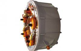
Motors and drives: nacelles on utility scale turbines are filled with motors and drives. The latter devices are part of the turbine controls that tell motors what to do. Generally, electric motors pitch the blades on turbines with less than 1.5 MW outputs and point nacelles in appropriate directions. Utility-scale turbines can have up to eight yaw drives. Motor outputs on these turbines range from 2.2 to 22 kW. They attach to speed reducers to produce output torques from 2,000 to 50,000 nm.
Blade-load sensing leads to rotor monitoring and load measuring on the turbine hub. Such a system can be designed-in during manufacturing or retrofitted. The system detects operation and maintenance issues such as blade icing, in which the system lets operators predict when they ought to shut down turbines because “ice throw” is possible. Signaling when the ice has been shed from a blade also lets operators restart sooner.
Such controls and sensors would allow for adjustments to:
• Yaw misalignments. When running below rated power, a 10° yaw misalignment reduces power output by about 5%.
• Rotor imbalance. Sensors that provide data on mass and aerodynamic imbalances allow early action to maximize power generation and avoid damage.
• Blade damage. Sensors can detect damage affecting the structural or aerodynamic performance of a blade, allowing early remedial action.
Inverters
The output from a generator has three electrical characteristics: voltage, current, and frequency. Because wind speed changes constantly, a generator would produce these at variable rates as well. Hence, the inverter’s job is to steady two of the characteristics, and let only one of them vary. These electrical devices turn the variable current or voltage coming out of a generator into steady voltage and frequency that can contribute to power on the grid.
Transformers
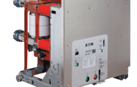
These allow raising or lowering voltage in ac transmission lines. Transformers for wind turbine generators switch with solid-state controls to limit inrush current. While potentially aiding the initial energization, these electronic controls contribute damaging harmonic voltages that, when coupled with non-sinusoidal wave forms from the turbine, also contribute to overheating.
Standard voltage alternates at 60 Hz. When the transformer frequency differs, voltage peaks do not line up and do not produce the required amplification that would come from in-synch frequencies. The transformer tries to pass its voltage through the circuit, thereby causing extra loading. All electronics today send spikes on line. Transformers must handle the higher loading in frequency disturbances and spikes.
To handle potentially hazardous heat, one transformer manufacturer winds coils on a cruciform- mitered core. Circular windings have coolant flow ducts throughout which evenly spread radial and axial forces over their circumference, eliminating hot spots that lead to premature breakdown and ultimately transformer failure.
Transformers for wind turbines are usually designed so their voltage exactly matches the wind turbine’s output voltage. Generator output current is monitored at millisecond intervals. Operational limits allow up to 5% over-current for 10s before controls take a generator off the system. Because transformers used with wind turbine generators are intended to match generator output without overload sizing, the generator must function without extra capacity.
When using a rectifier-chopper system (the electronic controller in wind turbines) the transformer must handle harmonics similar to rectifier transformers. These harmonics are called “dirty” because they may contain high frequencies that wind-farm owners do not want to send to the grid because they affect other equipment.
Filed Under: Generators


