 Steven Leidig
Manager of Enclosure Engineering
Crenlo
Rochester, MN
www.crenlo.com
One of the most important components for delivering wind power to the grid is the electrical inverter. The wind could blow at the optimum speed, but if the inverter is not converting power to its full potential, the cost of lost efficiency passes to the owner.
Several environmental and situational factors can negatively affect an outdoor inverter’s efficiency. Unfortunately, there is no one-size-fits-all solution for inverter protection. However, manufacturers of inverters and inverter enclosures have collaborated in the design process so that wind farm operators can choose a best solution in four areas critical to efficiency: airflow and cooling, environmental protection, operations and maintenance, and electromagnetic interference.
Airflow
Electronics run most efficiently within a predetermined temperature range. If the temperature strays from that range, electronic performance suffers, potentially resulting in a full shutdown and shorter component life. This is particularly true for inverters, which generate significant waste heat, and are often subject to harsh environments.
Regulating the temperature of an inverter is less about cooling and more about airflow than one might think. The best way to keep an inverter at its proper temperature is to move the waste heat away from the electronics, rather than blow cold air at them. Determining the exact amount of airflow necessary to remove that waste heat from the inverter enclosure in cubic feet per minute (CFM) can be a challenge, and entirely depends on the size of inverter and the ambient temperature range of the region. Consider two identical inverters. They may have the same design, but their enclosures could differ greatly depending on where they are installed. What might be a good enclosure on a wind farm in the Rocky Mountains probably wouldn’t work for one in El Paso, Texas.
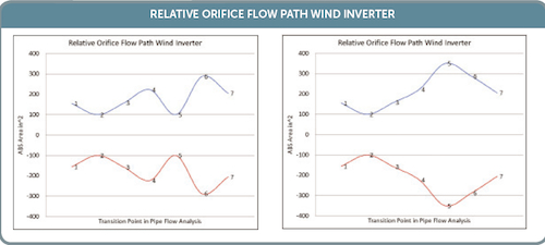
Factoring in the inverter’s size and the waste heat it will generate, as well as the ambient temperature range, lets engineers choose a blower rated to move air at a sufficient rate. All blowers have an established CFM rate. However, such labels are often misleading, because the blower’s manufacturer has no idea how and where it will be used. For this reason, it’s important to complete a standard pipe-flow analysis of the inverter enclosure to account for potential losses in airflow resulting from turns in the airflow path.
A standard pipe-flow analysis is an examination of airflow speeds throughout the enclosure, from the air intake all the way to the exhaust. Measuring the pressure and velocity at the air intake, data logging anemometers account for frictional losses in speed as airflow passes through orifices and turns corners. The final analysis at the exhaust will help the engineer determine how best to size, space, and sequence all orifices and turns in order to achieve maximum airflow efficiency within the inverter enclosure. Also, because the location of the air intake and exhaust may differ from installation to installation, potential losses in airflow should be analyzed for each application. Doing so helps determine the appropriate blower size.
While blowers pushing air through an enclosure can ensure waste heat removal from the overall structure, some components need more attention. Printed circuit boards (PCBs) and other critical electronic components are extremely sensitive to heat and require a targeted approach in a sealed and controlled environment. Housed in a separate and sealed cabinet, the PCBs should be regulated with heat exchangers that transfer heat out into the main cabinet, which the blowers then remove. This extra heat exhausted into the main cabinet should be considered when initial pipe-flow analysis takes place.
Environmental protection
In addition to temperature, environmental factors such as dust, insects, rain, sleet, snow, and humidity can damage the inverter or impede its efficiency. This is why materials used on the enclosure are important to the inverter’s longevity and function.
The National Electrical Manufacturers Association (NEMA) issues enclosure ratings based on their ability to protect from these environmental factors. At minimum, exterior enclosures should be rated as a NEMA type 3R. This rating is given to most outdoor air conditioning units, indicating that it is rainproof and water will not contact live wires. This is a sufficient solution for warm and mild conditions that don’t experience prolonged freezing or major corrosion concerns. Harsher conditions often require a higher level of protection from extreme environmental factors.
Excessive freezing and snow are major concerns for wind farms in the upper Midwest, such as Iowa, Minnesota, and the Dakotas. A NEMA type 3S enclosure offers additional protection, ensuring that internal components continue functioning when the enclosure is covered with ice. Also, the structural integrity of the enclosure must be sufficient to support the weight of ice and snow.
However, NEMA type 3R and 3S enclosures do let moisture into the cabinet. By the very nature of the cooling and airflow design, a cold-plate atmosphere forms. Condensation forms in the main cabinet. It’s important to understand where the condensation will form and where it will drip, to ensure there are drain-holes below that location and on either side of it, because level mounting during installation isn’t always guaranteed.
The critical electronic components of an inverter (such as the PCB and wiring), should be housed in a separate and sealed enclosure within the main cabinet. Moisture will cause wiring oxidation, and dust can impede connections. A NEMA type 4 rating is recommended, because it indicates the enclosure is watertight and dust-tight. In environments where corrosive agents are present, such as saltwater in the air, a NEMA type 4X enclosure would be suitable for the PCB and wiring as additional corrosion protection.
Though it would be nice to use a watertight and dust-tight enclosure for the main cabinet, the necessity of airflow makes the NEMA type 4 or 4X unsuitable options. This is why choosing the right materials and finishes is important.
Enclosures are typically made from steel or aluminum. Steel is the cost-conscious choice, but aluminum offers better thermal and corrosive protection. So, for offshore settings or those that experience temperature extremes, aluminum is the preferred material.
However, some finishes can be applied to steel for additional protection. Full-immersion primers are generally more effective than spray-on primers. Epoxy electrocoat (e-coat) is an example of a common and effective full-immersion primer.
Operations and maintenance
Ease of maintenance is important to the inverter’s longevity. Accessibility and ease of use concerns should be addressed during design and installation phases. The end user should be cognizant of the type of work that will go into regular maintenance and ensure the enclosure’s parts, such as filters and fuses, are easily accessible.
However, much of an inverter’s inspection is done remotely through wireless monitoring. Such a monitor can send information to the wind-farm operator on everything from temperature, airflow analysis, power input, and power output. Sensors are often built directly into the PCB to shut the inverter off if it reaches temperatures that are too high. Most wind-farm operators would agree with the procedure, but it’s preferable to catch a problem before downtime.
An inoperable inverter can pose other problems besides lack of power production. Without airflow, an enclosure provides a nice warm home for insects and rodents, which can impede future airflow and damage wiring. Hence, it’s recommended that all orifices be plugged to avoid unwanted inhabitants.
Also, without proper airflow, harsh temperatures can damage internal inverter components beyond repair. Monitoring is necessary to avoid unplanned downtime. However, placing the wireless data transmitter in an enclosure can severely impede its ability to relay vital performance information to the wind-farm operator. Lastly, shielding for electromagnetic interference (EMI) must be taken into consideration.
Electromagnetic interference
Inverters emit EMI that can disturb transmission frequencies in the immediate area, including radio and television reception. Federal Communication Commission regulations require enclosures to shield the EMI made by inverters, and various other electronics, to certain attenuation levels. This is a problem for wireless transmitters, because anything within the enclosure is shielded from emitting frequencies.
Many times wireless transmitters are an add-on from the wind-farm operator, not something originally integrated into the inverter enclosure. Therefore, it is often placed inside the shielded enclosure, but this severely inhibits its signal strength. On a sprawling wind farm, this could mean problems go unnoticed for long periods of time. Wind-farm operators planning to use wireless monitoring should ensure their enclosures have a separate, unshielded box for the wireless transmitter. This is an important consideration for the design phase, further demonstrating the importance of collaboration between end user and the manufacturer of the inverter and enclosure.
WPE
Filed Under: Construction, News, Turbines

