By Simon Alain, Senior Product Manager, Scanners and Inspection Solutions, Olympus
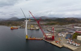
In operation, a wind blade is subjected to considerable lift forces. To ensure the essential shear strength of the blade assembly, the top and bottom blade shells are bonded together, supported by a set of shear webs. The spar cap, the part of the shell that is bonded to the shear webs, is usually made of thick glass fiber-reinforced material (GFRM) or carbon fiber-reinforced material (CFRM) for additional structural solidity. The integrity of the wind blade is highly dependent on the quality of the bonding between the shear webs and spar caps.
To verify the material and bonding integrity, application-specific low-frequency phased array (PA) and ultrasonic testing (UT) inspection solutions exist.
This article presents a variety of these ultrasonic solutions, examining each of their advantages and effectiveness for spar cap and shear web bonding validation.
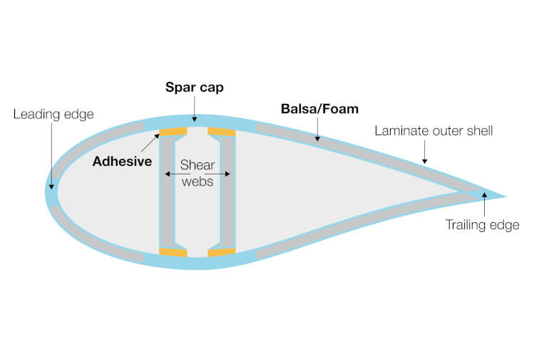
Typical cross section of a wind turbine blade
Issues with Inspecting Spar Cap and Shear Web Bonding Using Ultrasound
The structural complexity of wind blades and the acoustically unfriendly nature of the assembly materials can be ultrasonic inspection hurdles. The fiberglass and epoxy typically used in wind blade fabrication rapidly attenuate the ultrasonic beam, making PAUT examination challenging. The adhesive used to bond the shear web and the spar cap varies in thickness, and there are two interfaces that must be examined: (1) between the spar cap and the adhesive and (2) between the adhesive and the shear web. Since standard probes and holders are not adapted for wind blade inspections, PA and UT solutions have been developed that feature optimized probe and holder designs.
Proposed PA and UT Solutions
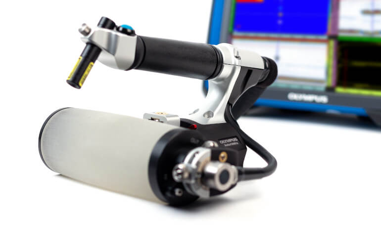
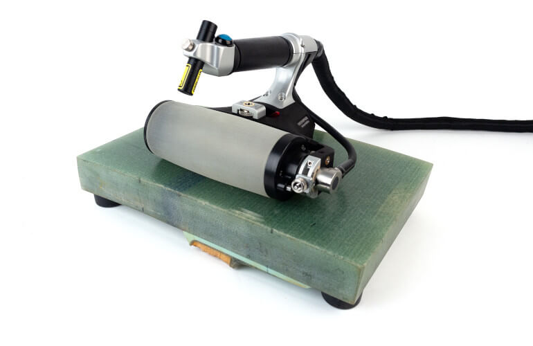
Phased array wheel probe and scanner
With a 1 MHz low frequency and 13-mm (0.51-in.) aperture, the integrated PA probe of this rolling scanner offers good penetration in attenuative materials such as composites. Its 128 elements with 1-mm (0.04-in.) pitch are multiplexed while scanning to provide a wide coverage. This helps reduce the number of passes required when scanning large wind blades. It also features a laser guide, an embedded encoder, and buttons to start the data acquisition and for indexing when 2D mapping. The liquid-filled tire is made of material with an acoustic impedance like water, removing the need for a couplant supply system.
PA probe and probe holders
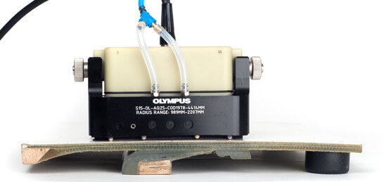
This solution is based on a large-aperture, low-frequency phased array probe mounted on a holder. The probe comes in 0.5 and 1 MHz frequencies with a 22-mm elevation and 1.5-mm pitch, optimizing beam penetration in thick, attenuative materials. The holder can be fitted with an encoder for manual encoded inspection or mounted on a semiautomated scanner for 2-axis mapping. Like with the wheel probe scanner, the ultrasound is multiplexed across the probe’s elements to maximize the coverage.

A semicontact holder can be used for thicker sections of the blade, since its high-energy beams penetrate deeper into the part without repeated surface echo. The drawback is an increased dead zone close to the surface. A 25-mm (1-in.) Aqualene delay line holder can be used for thinner components (up to 40-mm [1.6-in.] thick) for better near-surface resolution. These holders can be contoured to scan along the length of the blade or flat to scan across the width.
Delay line UT transducer and holders
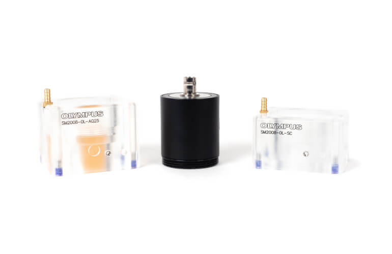 Conventional ultrasonic testing (UT) technology is practical for targeted areas of the wind blade, when coverage and C-scan resolution are lesser concerns. Two holder options are considered here: a semicontact holder to inspect thicker parts and a holder with a 25-mm (1-in.) Aqualene delay line to achieve a good near-surface resolution on thinner parts. The UT transducer and holder can be mounted on an encoding scanner or 2-axis semiautomated scanner. However, mapping a large surface will take more time than with a larger aperture PA probe.
Case Studies Using PA and UT Wind Blade Inpsection Solutions
To validate the performances of each of these solutions, three different tests were performed using a flaw detector with both PA and UT capabilities.
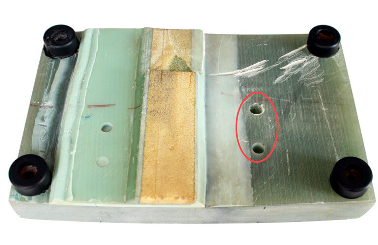
Test 1: Thick Spar Cap Volume Inspection
These tests were performed on a sectioned sample of a wind turbine blade featuring two 12.5-mm (0.5-in.) diameter flat-bottom holes (FBH) positioned at 16-mm (0.6-in.) and 32-mm (1.2-in.) deep. These manufactured flaws simulate delamination within the volume of the spar cap.
Results
Phased array wheel probe
In images produced using the data acquired by the phased array wheel probe (Olympus RollerFORM XL scanner), both indications are easily detected and imaged in the S-scan and amplitude C-scan.
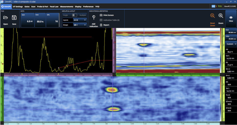
A-scan, S-scan, and amplitude C-scan data acquired with a 1 MHz wheel probe scanner
Phased array probe and delay line probe holder
Although, the semicontact holder would have been a more logical choice for this sample, the holder with the Aqualene delay line was used with the 1 MHz probe (I5 model) to provide more comparable results to the wheel probe scanner. The following figure shows the results obtained with this configuration. Both indications are easily detected and imaged in the S-scan and amplitude C-scan.
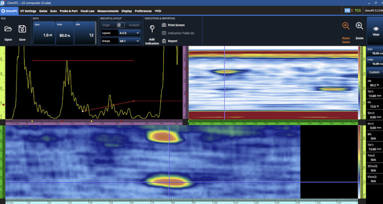
A-scan, S-scan, and amplitude C-scan data acquired with a 1 MHz phased array probe and holder with an Aqualene delay line
M2008 UT transducer and delay line holder
![]()
Again, the holder with a delay line was chosen instead of the semicontact holder in order to provide results that can be compared with the wheel probe. Although it resulted in a slightly reduced depth resolution, the transducer’s low 0.5 MHz frequency provided an excellent signal-to-noise ratio (SNR) as it was less affected by the multiple layers in the material.
A-scan, B-scan, and amplitude C-scan data acquired with a UT transducer and delay line holder
Test 2: Shear Web Bonding Inspection
Tests were performed on a wind blade in manufacturing using a customized 2-axis encoded scanner fitted with the 1 MHz PA probe and semicontact holder.
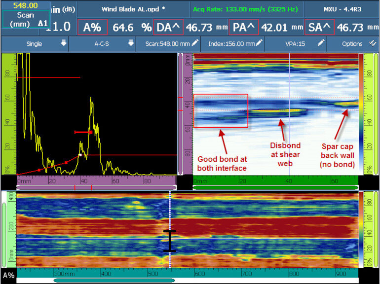
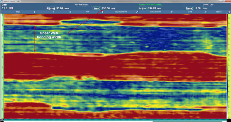
The C-scan offers a comprehensive view of the bonding of the two shear webs. The two blue lines represent the bonding interfaces of the shear webs with the spar cap. The ultrasound beam propagates in the shear webs, resulting in a lower amplitude for the return signal. The C scan can also be used to measure the width of the bond using measurement cursors. In this test, the width was approximately 130 mm (5.1 in.). The red areas represent where there is no bonding. There, we observe that the reflected signal from the spar cap back wall is strong.
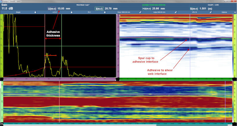
The adhesive layer was thick enough that both interfaces can be distinguished. Using the measurement cursors in the S-scan and A-scan views, the adhesive was determined to be 15-mm (0.6-in.) thick.
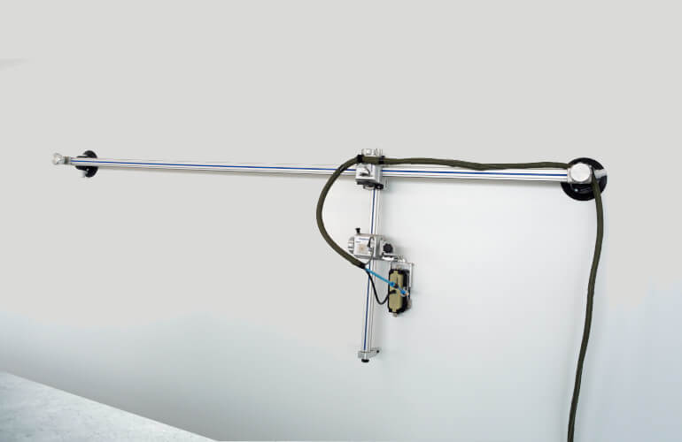
To inspect large areas on wind blades, the use of a semiautomated 2-axis encoded scanner can be beneficial. A long scanner, such as the GLIDER scanner below with a total stoke of 1.8 m (72 in.), can be placed along the length of the wind blade. The second axis should be long enough to cover typical shear web configurations.
Test 3: Thin Spar Cap Volume Inspection
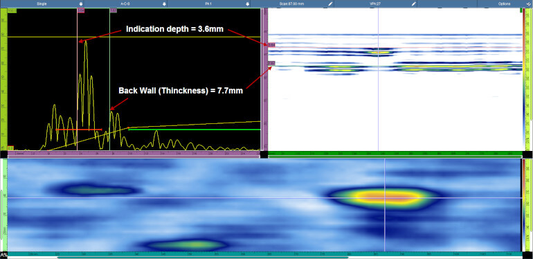
This test was performed on a sample featuring a 12.5-mm (0.5-in.) flat-bottom hole (FBH), simulating lamination in the spar cap. In this case, the spar cap is relatively thin (7.7 mm [0.3 in.]). For that reason, the 1 MHz PA probe was paired with the Aquelene holder because of its ability to detect defects closer to the surface.
The scan results clearly show the simulated defect located at 3.6 mm (0.14 in.) under the surface.
Overall Advantages of Ultrasonic Wind Blade Inspection Solutions
Although the acoustic attenuation and shape and structure of wind blades makes them a challenge to inspect, these PA and UT solutions overcome these issues while providing high-resolution data and imaging. Inspecting the structural integrity of wind blades can benefit from all the advantages of phased array ultrasound, enabling higher PODs and less operator-dependent inspections. When deciding which solution fits your needs, consider that the wheel probe scanner is more convenient for parts up to 40-mm thick, while the 1 MHz PA probe solution performs better on thicker, more attenuative materials. The UT transducer solution is practical for targeted inspections of the wind turbine blade, however, the probability of detection (POD) for defects is not as high as when using phased array.
 Simon Alain (BSc) is Senior Product Manager, Scanners and Inspection Solutions, for Olympus. In his more than 14 years at Olympus, Simon has overseen the introduction of numerous innovative portable scanning devices and inspection solutions, bringing improved ultrasound data acquisition to the market.
Filed Under: Featured