The three drive-train components that fail most frequently are the main bearings, gearboxes, and generators. All are lubricated, yet oil analysis focuses only on the gearbox. Keep in mind that a wind-turbine gearbox is a box with gears, bearings, and oil. So what’s to fail? Gears, bearings, and of course, the oil.
Two techniques in the condition-monitoring toolbox stand out for providing insight to oil condition in a wind-turbine gearbox. One method draws a sample of oil for testing while the other uses an oil sensor. The major differences between these two are sample frequency and the type of data provided. There are pros and cons to each.
On-line oil sensors
These come in two types: Sensors that monitor the oil’s condition or chemistry are capable of detecting viscosity, oxidation, and water contamination. Sensors that detect the condition of the gearbox do so by detecting wear debris, contaminate, or particles carried in the oil.
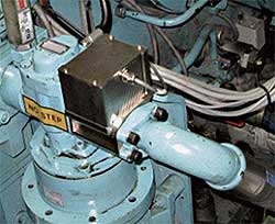
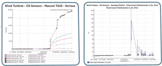
On-line oil particulate systems (wear debris sensors) are installed on the gearbox on either a primary oil-feed line or secondary oil-feed line to monitor the presence of particles in the oil. As bearings and gears degrade, they produce wear debris. If there are metal pieces in the oil, there must be a problem with either a bearing or a gear.
Problems with the technology as it applies to wind turbines, revolve mainly around their operation. Oil debris sensors which perform well in a steam turbine or other steady-speed application, produce very linear trends because they are in continuous operation for long periods. Wind turbines work on different schedules. They start and stop, run fast and then slow. They operate at an unsteady state, so trends are more difficult to interpret.
Operational conditions that affect oil-sensor readings include:
• About 60% of the time, wind turbines are not running
• Wind speed varies from season to season
• Temperatures, which affect viscosity, vary greatly from season to season
• Viscosity also varies from oil manufacturer to oil manufacturer
• Temperatures change greatly from stopped to running in day-to-day operations
• Physical access to maintain or clean the sensors varies among turbine manufacturers
A criteria based upon speed (rpm) or temperature stabilization would greatly assist in qualifying the oil-condition data. A speed signal would allow taking data only during the 40 to 45% of the time the turbine is running, thereby eliminating the 55 to 60% of the time when it is not running. And temperature stabilization would reduce the amount of variability in sampling due to viscosity. Cumulative counts of wear debris can also be helpful as a quantifying tool.
This is not to say oil sensors are inappropriate in wind turbines. On the contrary, they provide useful data on the oil condition or gearbox condition, or both. Wind turbines are not easy on the condition-monitoring analyst.
Six to eight companies manufacture oil debris sensors with a range of different features, installation locations, and type of data generated. Some sensors can discern between ferrous, non-ferrous, particle size, and type of contaminates.
Oil testing
While oil debris sensors continuously monitor for evidence of debris, oil testing involves drawing a sample and having a laboratory run several tests on the oil’s condition, and possibly the condition of the gearbox as well. Oil is typically tested for the presence of wear metals, contaminants, and the manufacturers wear-additive package. Several tests provide a range of information. The most common includes a total-acid number (TAN), total-base number (TBN), viscosity, particle count, wear debris and contamination.
Oil monitoring gets more complicated when you consider there is no single standard test for all wind turbines. “The suite of tests we perform varies from client to client,” says David Frycki of Herguth Labs, an oil-testing company. “For example, a GE 1.5-MW turbine may use a different test for each different gearbox used in that model. Castrol has a specific test just for its A320 synthetic Optigear oil. And Vestas turbines will use four to five different tests specific to the four to five different oils it uses.”
The ASTM D2270 viscosity test, for instance, determines whether or not a correct oil has been used. This test involves measuring the viscosity index (VI) of oil between 40 and 100°C.
Other challenges to getting good oil-test results include:
• Having access to the tower during production periods
• Difficulty in regularly accessing gearboxes (They are 60 to 90 m up a tower)
• Time delays between acquiring a test sample and getting its test report
• Getting consistent gearbox conditions from turbine to turbine
These challenges limit the frequency of sampling. In addition, another difficut-to-manage variable comes by comparing data from a turbine that was running to one that was not. The detailed data, however, can be quite good.
Be mindful that these sensors and tests focus only on the gearbox and not the main bearing or generator. The data gathered will point to a problem or confirm a problem. In other words, using either a test or sensor may also indicate a failing bearing. However, you may not know which bearing is failing in the gearbox, or if it is an up-tower repair.WPE
Filed Under: Lubricants

