 Cables in the wind industry fall into three categories: In the nacelle for signals and power, lightning protection, and balance of plant cables from turbine transformer to the collector.
In the nacelle, cables carry low-voltage control signals, data, and communication signals. Other cables carry power from the generator down tower to switch gear at the tower base. The issue surrounding cables in the nacelle is their flexibility at low temperatures, and oil resistance. Resilient cables for wind turbines should be Wind Turbine Tray Cable (WTTC) approved, and NFPA 79 (12.2.2) rated for constant flex.
Cables should have a torsional and bend high-flex life that meets the OEMs’ cold-bend test, with a flex rating to -40°C. The reason for the flexibility at low temperatures is that 600V power cables from the generator drop a couple meters below the nacelle in a long loop that lets the nacelle turn without winding or stressing the cable. Insulation at low temperatures can crack when flexed exposing conductors.
Cables in nacelles should also be oil-resistant because of occasional exposure to hydraulic oil, and more likely exposure to gearbox oil. Insulation can harden or swell with exposure to lubricants and expose conductors with sufficient wear.
A recent rating for tray cables, TC-ER (tray cable, exposed run) was prompted from changes in NEC and UL standards. When a basic UL cable meets additional crush and impact requirements, UL lets a manufacturer add the -ER suffix to the basic cable listing. The ER says the cable meets physical toughness requirements that allow exposing the wiring in particular applications. Wiring installed outside a tray is referred to as open wiring.
One manufacturer pointed out a few trends in the wind turbine cables. The biggest trend is that European turbine manufacturers setting up shop in the U.S. are looking for North American standards and UL approved designs, so there is movement from European IEC cable requirements to UL type requirements. In many cases it is not a smooth transition because UL cables tend to have larger diameters. The U.S. has developed material-based specs that call for a certain type of material at a certain thickness for a certain voltage. In Europe, IEC standards are performance based. There is less concern for how small or thin a cable is as long as it meets the performance spec.
To ground a wind turbine, a cable that is essentially copper-clad steel provides an alternative to solid and stranded copper. The conductor has an outer sleeve of copper metallurgically bonded to a solid-steel core. Its manufacturer claims cost efficiency and anti-theft characteristics. The cable is said to provide a safe, reliable alternative to the use of solid and stranded copper for grounding applications.
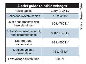
Balance of plant: One medium-voltage-power cable (15 to 45 kV) for underground distribution is manufactured and tested in accordance with ANSI/ICEA S-94-649 for Type URD concentric neutral and flat-strap cables. Conductors come in solid or class B compressed, concentric-lay stranded aluminum or copper, meeting appropriate requirements of ICEA and ASTM. Stranded conductors can be blocked to prevent the movement of moisture along the cable.
An alternative to direct buried cable or pulling cable in rigid conduit is cable pre-installed in a flexible duct. One such product offers mechanical protection comparable to rigid polyethylene duct and saves on the labor needed to pull cable in a rigid duct.
A few medium voltage options include a copper conductor when more current capacity is needed. Compounds can limit the intrusion of water into the conductor during manufacture, storage, installation, and use. An EPR Type III, 105°C rating allows a slightly higher current capacity for some installations. Flat-strap neutrals reduce overall cable diameters and can provide more protective coverage over an extruded cable core. Red stripes identify medium-voltage power cables. Lastly, semiconducting jackets provide an electrical connection with the earth in direct burial applications, which allows reducing ground rods per mile in accordance with the NESC.
Filed Under: Cables & connectors



This article is very interresting. I Have a question about the shield. For a motor (not the generator) inside the nacelle, operating at 120VAC or 480VAC, and instruments operating at low voltage like 24V inside the nacelle too, which type of cable should be use ; it is nacessary to have a braided shield over’all for all cables? How to correctly connect the shield (drain wire or over’all shield) considering the lightning that can hit the lightning rod?