Editor’s note: An earlier version of the Ocean Going Deck Barge and its operation is described here: https://goo.gl/Sz04s9 AMF Concepts has revised its design to use a catamaran for the barge to simplify buoy and WTG construction and deployment along with greater stability.
U.S. deepwater offshore floating wind turbine foundation platforms are taking too long to develop. We need them now. One design is readily available.
Andrew Filak / AMFConcepts
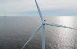
At present, 58% of the U.S. population lives in coastal areas. The National Renewable Energy Laboratory estimates there is potential for 4,233 GW of clean energy off the coast mostly in deep water. The figure is four times the capacity of the U.S. electric grid. The first fixed-bottom offshore wind farm in U.S. waters is now capturing this clean energy off the coast of Rhode Island. This project is now part of the 50 offshore wind farms operating worldwide.
The first offshore farm was in place in 1991 off the coast of Denmark. This puts the first U.S. offshore farm 25 years behind and makes a sad cometary for a country that has been first in so many industries.
What comes next
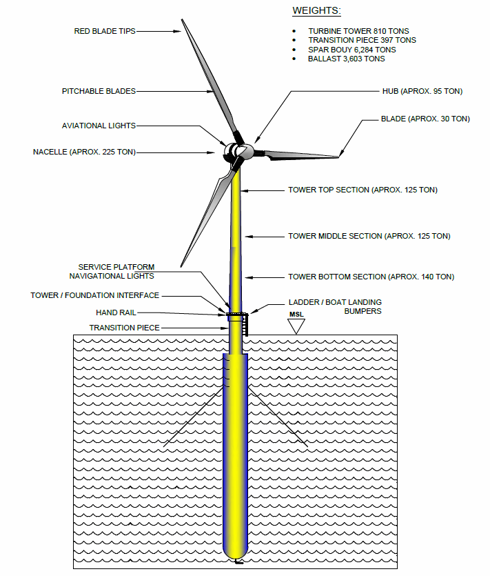
The illustration identifies a few spar buoy and turbine details for a deployed wind turbine. Pick on any of the images here for a larger version that is easier to read.
Now that a first offshore wind farm is harnessing energy from stronger consistent winds, we can bid on deep water lease developments using the forth coming 10 to 20 MW direct-drive wind turbine generators (DD/WTG). Major manufacturers are confident that these new direct-drive generators will be operational in the next two to three years. They will maximize the power per turbine while leveling cost. By one estimate, nacelle hubs will stand roughly 400 ft above sea level turning rotors with 600-ft diameters. The size of these turbines will produce a strong visual impact and for that reason, people will oppose building the wind farms off our coast. However, siting the wind farms at least 25 miles offshore will reduce this impact to the size of a dime at arm’s length. The turbines will blend into the sky because blades and tower are typically painted light gray or off white.
Choosing the correct floating platform to support the turbines
The concern is for how well a floating platform provides stability to counter the large mass, weight, and area aloft of the new DD/WTG’s. The consensus of developers working with the designers and universities is that the Spar Buoy design offers one of the best solutions as a floating substructure for turbine foundations.
This structure, characterized by a small water-plane area and a large cylindrical mass below the surface, has found increased favor in deep-water applications. Spar buoys have been designed for installations in depths of 400 to 2,400 feet. The buoys’ draft of 360 feet below mean sea level helps resist the heave motion. Ballast placed low in the buoy gives the system a low center of gravity, making it quite stable and resistant to pitching and rolling motion assisted by its station-keeping design.
Comparing the two spar buoy systems
The European spar-buoy export
This is a product of Statoil of Norway, an oil and gas company that has done an excellent job in transposing its know-how into deep water offshore wind farms. Its Spar Buoy (SB) is manufactured of heavy steel plate in a large steel fabrication plant. After a three to four-month production time frame, depending on source, the SB at 311 ft long, and 46-ft dia., 3,200 tons plus 1,000 tons of high strength concrete ballast, is transported out of the plant on a large gang of motorized dollies. They are then taken to a designated load-out position at the quay.
After placing the buoys side-by-side on a semi-submersible vessel, made fast to the quay, the buoys are transported to a final staging area. After floated off the semi-submersible vessel, the SB’s are towed, one at a time, to deep water for up-ending to a vertical position.
The spar buoy is then towed and secured to a ballast placing vessel. Here, iron ore ballast is crammed into the SB. At the staging quay, a turbine-top structure is fully assembled for lift off, by a large crane vessel for final assembly onto the SB. It is then rigged for a tow to the hook-up point in the wind farm. Statoils’ manufacturing, transport, assembly, and deployment require a high residency (a long period) at sea as well as time to work within an acceptable sea-state window. Their turnkey cost in 2018 for a 7-MW deployment is $50 million
The U.S. spar buoy concept
This construction and deployment system for Direct Drive, Wind-Turbine Generators (DD/WTG) offers developer of deep-water offshore wind the potential to capture this market with significant cost savings. This is achieved by delivering a fully assembled 7-MW DD/WTG to a deep-water site at a turnkey cost in 2018 for $35 million.
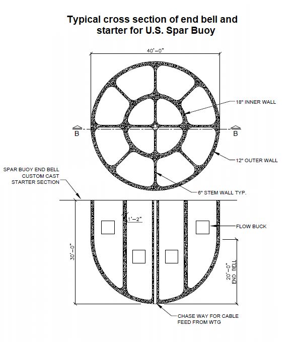
The end bell provides a starter section for the rest of the spar buoy which will be slip formed on top of the bell.
The turbine, station keeping, power-feed costs are the same for both systems. The significant differences are in the construction of the Spar Buoy, assembly and commissioning of the turbine, transport of both components to the site, along with tie down, and placement, of the DD/WTG atop of the buoy.
The U.S. design cuts significant costs (saves) this way:
- Construction of the U.S. Spar Buoy (USSB) foundation component is built on top of a self-contained, self-powered Ocean-Going Deck Barge (OGDB) with its own production system. The Spar Buoy (SB) is made by a slip-formed concrete construction method, similar to an extrusion. The method produces the most cost-effective buoy. This construction method addresses the major problem of forming a large round tube-type structure with internal struts tied to a second internal tube, making it easier to place rebar and concrete. The concrete mix design, to obtain a slip form rate of two feet an hour, can be achieved by changing from an ordinary Portland Cement (OPC, a binder) in the concrete from a wet cured to a dry cured formulation. The new cement binder, in the concrete mix, will be a Geopolymer which requires a heated formwork (85°F minimum) to dry cure.
This is a major advantage in production that provides fully cured concrete in 24 hours. Furthermore, it lets the slip form rise at four times its normal placement. This achieves a port-to-site production window of under two weeks for the construction and deployment of the turbine.
-
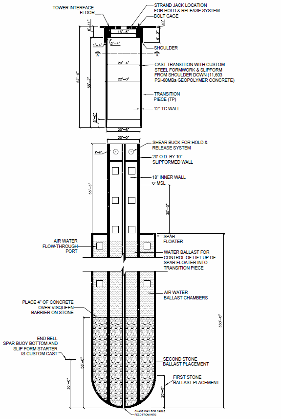
The illustration provides a closer look at a few internal spar buoy details.
The concrete is the basis of the USSB technology. For existing marine concrete structures, the greatest threat is water, either fresh or salt. Through time, water penetrates into concrete through unseen cracks and natural porosity and rusts the rebar skeleton. Even protective rebar has coating failures and deterioration which eventually allows the steel failure. Seawater also directly attacks the chemistry of OPC causing rapid failure. What causes the OPC binder to fail at sea is the high percentage of Calcium compounds (about 70%) that comes under attack by the Sulphur compounds in sea water. This rots the concrete. The cement binder in a concrete mix design can occupy up to 20% of the mass of the concrete.Replacing the OPC in the concrete mix design with a geopolymer binder will foil this degradation scenario by minimizing the calcium in its chemical composition. The geopolymer cement binder is made of four inexpensive and widely available components: Type-F fly ash, fresh water, waterglass (sodium-silicate), and lye (Sodium-hydroxide). With the type-F, low-calcium fly ash, the binder can have as little as 2% calcium producing a saltwater-resistant material.
Geopolymer cement binders are commercially used elsewhere in the world due to their superior performance to OPC binders. In general, these cements are stronger, as well as fireproof and waterproof. They bond well to most materials, have minimum expansion or contraction, and are resistant to salts, acids, and alkalis. Furthermore, the production process for geopolymer has a carbon footprint about 80% lower than standard OPC.
Instead of steel rebar, a nonmetallic bar made from readily available basalt will be used for the reinforcement. Basalt stone found all over the earth, is a key compound enabling the hundred-year minimum durability of the substructure. This time frame could allow using the foundation for three turbine generations). Heating basalt stone to 1,800°F turns it to a liquid that allows running it through a palladium die to produce soft flexible threads. The threads are laid in parallel and locked together with an epoxy, producing basalt rebar: a waterproof, chemical resistant, fireproof material with a tensile strength several times stronger than steel. The geopolymer binder in the concrete binds to the basalt rebar on a chemical level in addition to the mechanical bond.
The basalt rebar is extremely light and fairly flexible, lending to easy placement in the structure. Basalt fiber additives, much like nylon fibers, are used in the mix design for added strength. All internal steel jack rods, used to lift the formwork, will be extracted from the concrete. Leaving a steel free concrete structure.
The low porosity, high strength, and heat cured technology of the geopolymer binder in the concrete mix design give the SB substructure a minimum of a 100-year life.
Ocean-going deck barge with azimuth propulsion units and bow thrusters
A conventional spar-buoy structure becomes uneconomical due to the cost to slip it on land, its high weight, then to lay it down. Then the cost of ballast placement at sea adds more cost.
To avoid the expense of conventional methods, the Ocean-Going Deck Barge (OGDB) concept was developed and is key to the USSB system. It will be built to comply with the 1920 Jones Act, which allows only qualified U.S. vessels built domestically and crewed by U. S. citizens to carry cargo from U.S. port to U.S. port. The act was recently amended to include sites on the outer continental shelf where wind farms will be sited.
The OGDB serves as a construction, transportation, and deployment platform, all in one. With the barge made fast to the quay with ready access to materials and resources, the spar is slip formed at one end while at the same time, the WTG is assembled at the other. When substructure’s construction and top-side assembly are complete, the OGDB with its own propulsion will move out to the wind farm site with both components onboard. At the site, the spar is deployed at 50 foot an hour into the water, water ballasted down, and moored into location by standard station-keeping methods. The OGDB is rotated to position the WTGs’ transition unit over the spar, which is then de-ballasted, joined, and mechanically locked to the transition component supporting the WTG topside.
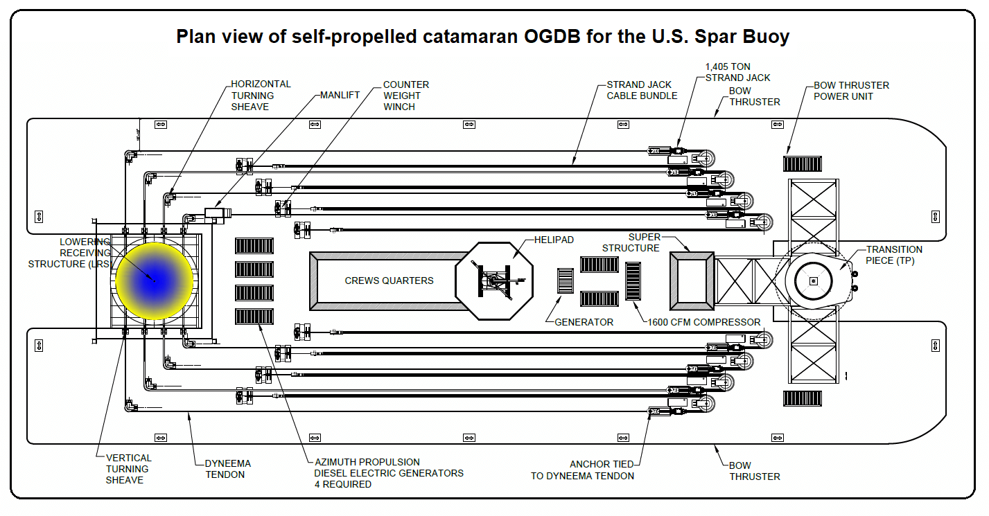
The deck plan (a top view) shows the winch cables, the spar buoy work area on the left and where the transition piece and wind turbine would sit on the right.
The OGDB is dual-hulled, a catamaran configuration with 480-ft LOA by a 170-ft beam, a 32-ft deck-plate-to-hull-bottom, and powered by two azimuth propulsions units. The OGDB is constructed with two hulls of 480-ft LOA by 60-ft wide connected by a bridging structure 300-ft by 50-ft by 10-ft deep flush with the deck plate and centered fore and aft on the outside hulls. This provides a deck plan of 72,600 ft2.
The weight of the barge per square foot, including the extra hard point structural framing, ballast system pumps, and piping is estimated at 600 lb/ft2, for a total of 21,780 short tons. (1 short ton = 2,000 lb). With a foot of draft displacing 2,323 short tons the unloaded barge will have a draft of 9.4 ft. The estimated deck load (with no spar or WTG loads) adds 3,700 short tons. Prior to spar production and WTG assembly, the ballast tanks will be filled with 12,084 short tons of water at the quay, bringing the total to 17.6 ft of load-line draft. The total weight before production at the quay is 37,560 short tons.
During the slip and WTG assembly, the ballast management system will pump out the 12,084 tons of ballast to maintain a steady draft and level deck surface as construction and assembly materials are loaded and positioned on the barge. When under way, with the spar construction and the WTG assembly complete, the OGDB load-line draft will remain 17.6 ft, with an under way freeboard of 14.4 ft.
There are two towers on the OGDB. The aft tower is for the spar buoy. This multi- functional structural tower is made up of high strength man-lift mast sections. The port side, forward leg of this tower supports a rack-and-pinion man lift. All four legs of this tower support a lift-up gripper-retention system. This gripper ring is raised up and engaged after the slip formwork stage has passed the half way point on the finished spar buoy. Integral with the tower is a lowering and receiving structure (LRS). The LRS frame is designed to support the end bell, constructed ashore, its weight, the spar buoy weight, and the stone ballast. The LRS is held in the tower over the aft slot of the OGDB by eight Dyneema tendons (designed for salt-water immersion). At the other end of the catamaran barge, over the forward slot, is the transition component supporting the WTG as it is assembled.
Construction on the barge
Buoy construction is supported and executed on the OGDB at the quay. The first component (cast on the land side) is the end bell started section. It has a 40-ft diameter by 30-ft height and is lifted down and set into the LRS well, with a one-foot diameter, indexing pin in the center at the bottom of the bell. Fine sand is placed to stabilize the set between the concrete end bell and the galvanized steel LRS. The next operation places stone ballast in the first 20 ft for added stability.
Next, the slip formwork and formwork staging are placed, in four pie shaped quadrants, onto the end-bell starter. The spar is then slip-formed 70 ft and then paused to place the remaining permanent ballast stone.
After placing a four-inch concrete cover on the stone, the slip is continued to the 330-ft level where the formwork is lifted off the outer hull of the spar, which allows releasing the stem framing from the final stage for continued slip forming of the last 60 ft of the stem.
While the spar is being slip-formed, the WTG is assembled at the other end of the barge. A transition component, supporting the WTG, is built around and cantilevered out over a bow slot. This slot supports the transition component with a lock and release system for mating to the spar buoy substructure. The WTG will be assembled atop the transition component, with close attention to managing the water ballast.
Once construction completes on the barge, it will be under way by its own propulsion out of the harbor to the installation site. With high windage on the spar buoy and WTG, the weather will be watched carefully to ensure that conditions and sea states are right for a safe transit.
Dynamic positioning
Critical to a safe and efficient operation, the catamaran OGBD is equipped with two azimuth thrusters aft and two bow thrusters forward, controlled by a dynamic positioning system that will hold the OGDB as the components are deployed. The dynamic positioning will have active wind and current compensation, thruster selection and enabling, power management, automatic heading hold, and other pertinent sensors. All the information sensors, data readout, video feeds, and manual and joystick controls for the entire OGDB will be housed and displayed on the control console in the third level of the super structure.
Deploying the spar buoy
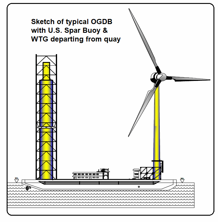
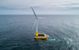
A completed spar buoy and wind turbine would look like this leaving the assembly quay for the deployment area.
Upon arrival at the installation site, the spar buoy is deployed into the water at a rate of fifty feet an hour. The total weight of the spar buoy, stone, and LRS will require eight liner winches to lower it into the water. Each liner jack is rated at 1,405 short tons with a 2.5 minimum safety factor. All are operated simultaneously from a single computer platform.
All are attached to Dyneema tendons that have a proven long life in salt water. The tendons, in turn, are attached to steel jacking strands that do not enter the water. There are 84 steel jacking strands in a bundle that weighs in at 98 lb/ft going through the jack. To keep the bundle tensioned, a synthetic rope is attached to a programmed winch. While the spar buoy is being lowered, the water ballast management system will control the deck leveling system, but in direct reverse to the construction and assembly phase. After a small lift to release the LRS’ hold and lock system, the Dyneema tendons lower the LRS, with the spar buoy, into the water. Upon reaching a free-floating condition and ballasting to a designated level, the station-keeping crew will tether it to the ocean bottom anchors.
WTG placement and support
The dynamic positioning system on the OGDB then positions the WTG topside over the substructure (the spar buoy) for an accurate lift-up and lock of the substructure into the transition assembly. The bow slot, under the top support structure, will receive the outer hull of the spar buoy. The sub structure is then slowly de-ballasted to raise it up and insert the stem, on top of the spar, into the transition section. This component is equipped with a lock-and-hold system for securing the substructure to the top side.
This assembly method eliminates the need for heavy marine cranes, minimizes open water residence time, and provides a means of changing out the turbine at a later date, or for returning the WTG to the quay for repairs that cannot be done at sea. Turbine replacement will be required every 25 to 30 years, according to the University of Maine. Reusing the foundation up to three times minimum make it extremely cost effective. The reinstallation of the turbine, by design, has been made completely reversible without affecting the station keeping of the spar buoy substructure.
Construction time and cost opinion
This opinion, with accurate input, identifies the unit cost at $5.2 million per turbine spar buoy (excluding the cost of the WTG itself) for construction, assembly, and delivery, in under two weeks, to a station-keeping crew in a 100-unit wind farm. This installation cost is a fraction of the current floating foundation cost.
Summation
The dry cured concrete U.S. Spar Buoy and associated ocean-going deck barge, with its own propulsion, are revolutionary approaches to greatly reduce offshore WTG capital and O&M cost. From this new material selection, which enables novel fabrication techniques in the offshore industry, to the unique barge enabling simplified transportation and WTG deployment logistics, these advances challenge the status quo in offshore wind farm development.
Additionally, the geopolymer concrete cement binder supports aggressive global carbon reduction by producing 80% less CO2 and in a much shorter fabrication process. The concrete is stronger and has a longer service life in salt water, which extends the life span and reduces overall cost. The offshore wind developer needs to step forward to take advantage of the USSB cost and its domestic and export potential.
Reach author Filak at amfconcepts@gmail.com or 310-373-5004
Filed Under: Construction, Offshore wind