Andy Filak, AMF Concepts
John Reeves, Marine architect
Mohamed Soliman, Ph. D. Consultant
The beauty of placing wind turbines offshore in deep water is that the wind farm consumes no real estate nor blocks a seascape view from land. Better yet, far offshore places turbines in steadier and stronger wind. Furthermore, this location and its winds also allow the use of larger turbines.
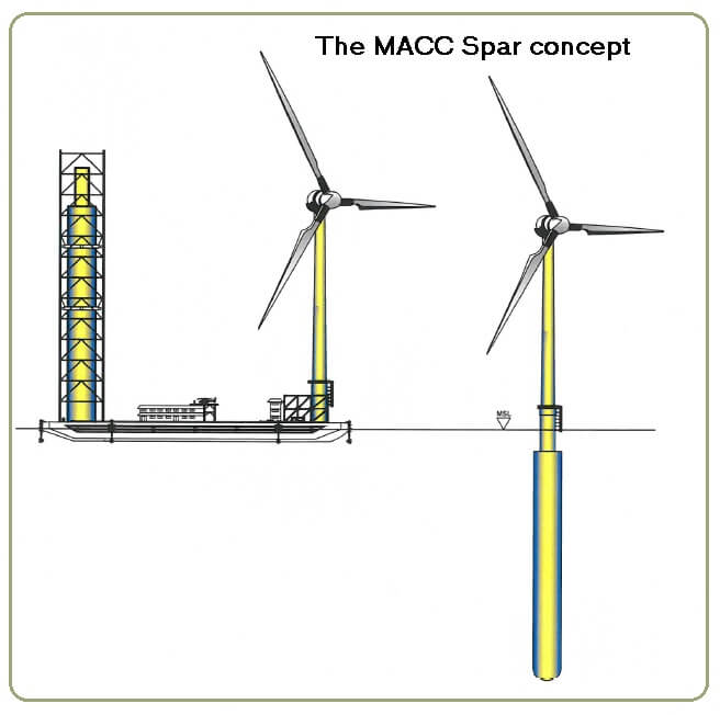
To make deep water installations more feasible, this article will describe a spar buoy or floating foundation system. The cost of its construction and deployment would be a fraction of the current foundation costs for deep-water wind farms.
The lower installation costs come from the way the spar buoy is produced and deployed. For instance, it is built on an ocean-going deck barge (OGDB) tied to the quay, then towed to an offshore site for final assembly and deployment. The station-keeping crew will tether the assembled unit to anchors on the ocean bottom.
Process overview
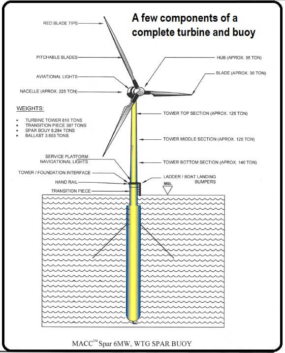
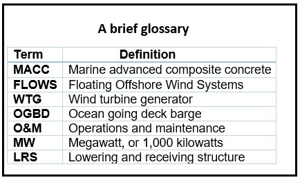
Our marine advanced composite concrete (MACC) and cost opinion are based on building and anchoring 100 Floating Offshore Wind Systems (FLOWS). Each FLOWS will consist of a floating sub-support structure and a large Offshore Wind Turbine Generator (OWTG). Each FLOWS will be anchored about 1,000 meters (3,300 ft) apart to eliminate or reduce wind shadow effects. The rotor on each 6 MW, WTG will reach 656 ft above mean sea level. The OWTG will be station kept on the ocean floor by six synthetic ropes tethered to three anchors.
Spar buoy construction
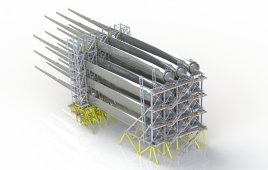
The proposed barge provides for the construction of the spar buoy and assembly with the wind turbine.
The key to the spar buoy construction system is based on:
- Marine Advanced Construction Concrete (MACC) which reduces Offshore WTG capital and O&M cost by using an ocean-going deck barge (OGDB). It will serve as a platform for the slip-formed concrete construction of the spar buoy and assembly of the WTG for the deployment.
- A concrete cement binder (geopolymer) to meet carbon reduction goals. Production of the mix will produce 80% less CO2 than conventional concrete.
- By using geopolymer cement as a binder in the slip-formed concrete (similar to an extrusion) will make for a high compressive strength, 12,000 psi, about 80 MPa in the concrete. Tensile strength comes from Baysalt rebar and Baysalt fiber. This is a waterproof, chemical resistant, and fire-proof material with a tensile strength several times stronger than conventional steel rebar. Baysalt rebar is ribbed, like steel rebar, to provide a mechanical grip. With geopolymer cement, the binder achieves a chemical bond as well. The lightness of the Baysalt rebar makes it easy to place in the pour.
Because the geopolymer concrete is heat cured there is no significant cracking during the curing. The weight of the geopolymer mix plus the weight of the Baysalt rebar increases strength while reducing weight, and weight reduces displacement.
The problem in the use of Portland cement as a binder in water is the water. Portland-cement binder has higher porosity in the concrete requiring more cover which is more weight.
Formwork systems
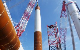
We studied the top designers around the world to arrive at the most cost-effective formwork system. The major problem encountered was forming a large round structure with internal struts tied to a second internal round with struts in a perpendicular mode. This is extremely difficult for rebar and concrete placement. Placing the final structure horizontally in the water calls for further structural requirements in the end product. The best production time frame of all the formwork systems studied was 41 days. Slip forming produced the most cost effected solution with a heat-cured formwork. This latter design can achieve a two-feet-per-hour slip and in seven days save 500 crew hours over the 41-day method.
Slipforming the spar buoy
Slipping the spar uses all of the standard methods except for the heated formwork and a Tremie Elephant Trunk, an 8 to 12-in. diameter hose needed to place the geopolymer concrete. The mix cannot be pumped due to the friction heat generation.
Placing the spar buoy in water
The cost to slip on land and achieve a lay-down of the structure becomes uneconomical because of the weight of the spar and the cost of placing ballast at sea. Consequently, the oceangoing deck barge came into focus as a solution.
Ocean going deck barge (OGBD)
The barge size and deck plan is 148-ft wide and 440-ft long with a 27-ft height, from deck plate to bottom. This, less the deck well cuts fore and aft, provide 60,120 ft2 of deck in the plan. The weight of the barge, including the extra hard point structural framing, ballast system pumps, and piping is estimated at 18,036 tons or 600 lb/ft2. A foot of draft for every 1,924 tons gives a draft of 9.38 ft. The estimated deck load adds 3,700 tons, (without a Spar or WTG).
This brings the new total weight to 21,736 tons, and a draft of 11.33 ft.
Prior to Spar production and WTG assembly, the construction will pump on 12,084 tons of water at the quay adding 6.23 ft to the draft bringing the total to 17.53 ft. The water ballast is necessary to keep the deck level during while slip forming the buoy, and when the WTG weight is added forward during the 10-day construction period. Sensors will automatically control the ballast function.
The total weight before production at the quay will be 33,800 tons. During the slip and WTG assembly, the ballast “Level Deck” management will pump out 12,084 tons of ballast, during a twelve-day period, at the quay. At tow out, with the Spar construction and the WTG assembly, now complete, will add weight bringing the OGDB draft to 17.58 ft., or a free board at tow-out of 9.5 ft.
Spar buoy substructure
The developers’ consensus is that the spar buoy substructure best meets the requirements for building deep water wind farms. The spar buoy offers a lot to potential developers such as:
1) It can be slipped formed as a seamless concrete displacement structure. It will have its steel jack rods extracted at the end of the slip producing a concrete steel-free structure.
2) The substructure will have a minimum of a 100-year life due to the low porosity, high strength, and heat cured technology of the geopolymer binder in the concrete mix design.
3) Because turbines wear out (optimistically) every 25 to 30 years, the University of Maine says the foundation, not the turbine, is the costlier of the two units. This foundation reuse, up to four times minimum, makes the Spar design extremely cost effective. The reinstallation of a turbine, by design, has been made completely reversible.
Placement and support of the WTG
The WTG support structure, built around and cantilevered out over the bow well, is intended to support the transition piece with a lock-and-release system for the turbine float out. The WTG will be assembled atop this transition piece with close attention to the water ballast release management. The bow well, under the top support structure, is designed to receive the outer hull of the spar (40-ft dia). During the substructure’s lift up, the stem (20 ft) on top of the spar, is lifted onto the transition section. This is the component that must hold (and later release) the substructure.
Spar buoy tower on the aft end of the OGDB
This is a multi-functional structural tower made up of several high-strength mast sections. The port side, forward leg, of this tower supports a rack-and-pinion man lift. All four legs of this tower support two lift up gripper retention systems. These gripper rings are raised after the slip formwork stage has passed the half and three-quarter points on the finished spar buoy.
Spar buoy lowering and receiving structure (LRS)
The callouts detail some of the assembly functions.
The LRS structural frame is intended to support the end bell (bottom) of the spar buoy, it’s weight, the spar buoy’s weight, and the stone ballast. The LRS is held in the aft well of the OGDB by eight Dyneema tendons (designed for salt water emersion). After a small lift to release the LRS’s hold and lock system, the Dyneema tendons lower the LRS, with the spar buoy attached, into the water.
Spar buoy construction
The spar buoy construction is supported and executed on the land side of the quay. The first component (built on the land side) is the end-bell starter section. It has a 40-ft. diameter and 30-ft. height, and is lifted down and set into the LRS well, onto a Turk’s hat shaped indexing pin, in the center of the bottom of the end bell. To stabilize the set fine sand is placed between the concrete end bell and the galvanized steel LRS. The next operation places stone ballast in the first 20 ft. for added stability. Next, the slip formwork and formwork staging is placed in four pie-shaped quadrants on to the end bell starter. After the slip has raised (forming the buoy) to 70 ft. it is stopped to place the remaining stone in as permanent ballast. The slip is then continued to the 330-ft. level where the formwork is removed from the outer buoy hull, to release the framing from the final stage, for continuing the last 60 ft. of the stem.
Lowering the spar buoy into the water
The total weight of the spar buoy, stone ballast, and LRS will require eight linear winches to lower it into the water. Each linear jack is rated at 1,405 tons with a 2.5 minimum safety factor. All are operated simultaneously from a single computer. All are attached to Dyneema tendons that have a proven long life in salt water, they, in turn, are attached to steel jacking strands that do not enter the water. Eighty-four steel jacking strands, in a bundle weighing in at 100 lb/ft, go through the jack. To keep the bundle tensioned a synthetic rope attaches to a 25-ton counterweight and then to a lifting winch. The counter weight is lowered through a tube in the hull of the OGDB and retrieved by the winch before tow back. During spar buoy lowering, the water-ballast-management system controls deck leveling.
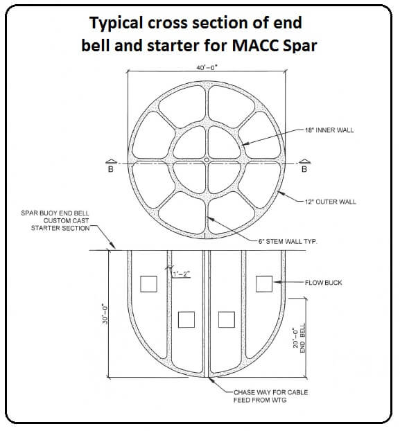
The cross section and side view of the end bell (bottom end) provide more detail.
Dynamic positioning and control
The OGDB is equipped with eight 500-hp hydraulic outboard thrusters fixed, with a protective frame, designed non-tilting with their containerized hydraulic power units. These thrusters will position and hold the OGDB over the substructure for an accurate lift-up. The thruster control is tied to the dynamic positioning system’s operational program. The dynamic positioning will include active wind and current compensation, thruster selection and enabling, power management, automatic hold heading, and other pertinent sensors. All of the information sensors, data readout, video feeds, manual and joystick controls for the entire OGDB will be housed and displayed on the control console in the third level of the superstructure.
Substructure lock-and-hold system
This system provides a way of holding the substructure to the transition component that supports the WTG. The system also provides a way to change out the turbine at a later date or to return the WTG for repairs at the quayside.
 Construction costs
This opinion identifies costs at $6.9 million to hand-off one turbine (excluding the cost of the wind turbine) to a station keeping crew in the wind farm. That figure may strike some as high, but consider that the recent Block Island wind project cost more than $250 million for five turbines or an average cost of over $50 million per turbine. Understandably, this was the first offshore project in the U.S. but the industry is not sustainable at such a cost per launched turbine.
Filed Under: Construction, Offshore wind