Editor’s note: Although this report is from 2009, it is a curious idea to reencounter as the U.S. builds its first offshore wind farm. We present the Executive Summary here and a link to the full report. Readers might also be interested in: A closer look at how pumped hydro stores excess wind power by Robert Bullard: http://goo.gl/tGnHce
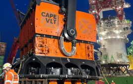
Delft University began a research project on using a 2 bladed, fixed pitch turbine (5 to 10 MW) to directly drive a water pump in the nacelle.
Delft University of Technology is taking a radical step away from incremental development of offshore wind turbines. It started (in 2009) a research project on using a 2 bladed, fixed pitch turbine (5 to 10 MW) to directly drive a water pump in the nacelle. By channeling the pressurized water of all turbines to one transformer platform, electricity generation is centralized.
The design goal is to reduce the number of components in the offshore turbines drastically to come to the ultimate offshore turbine. Current offshore wind turbines are marinized land turbines with only a few add-on features to keep out the salty air. Improvements of turbine technology are only incremental and do not take full benefit of the offshore environment. The Delft University of Technology has a history in offshore wind research of over 25 years and has formulated a radical concept change of offshore wind energy conversion that helps develop a completely new system and spark revolutionary developments on sub-system and component level.
Typically, offshore wind farms have a generator platform that gathers all electricity of the different turbines, steps up the voltage and feeds the power through shore connection cables to the onshore grid. The DOT takes boundary conditions from this existing configuration: horizontal axis turbine with blades and a platform where the combined electrical power is fed to the onshore grid. Everything in between can be changed. The DOTs focuses on radical technology changes. To facilitate this, a short list of design pointers has been defined to test all developments against and to keep as life line throughout the project execution. Offshore, one thing is abundant: water. The current turbine technology sees the nacelle weight increase steadily giving increasing challenges in support structure design and installation. Furthermore, power electronics help harness wind power slightly more efficiently, but also add weight and components (that can fail) to the turbine system.
Offshore wind energy has high potential. Currently the price for placing turbines offshore is too high. Projects are not yet economically feasible without government subsidies.
The overall goal of the Delft Offshore Turbines project is therefore to design a wind turbine infrastructure specifically for offshore purposes and thereby rendering offshore wind energy more economically attractive. This translates to a design goal of the overall project which is to reduce the number of components in the offshore turbines drastically to come to the ultimate offshore turbine, which is characterized by:
- Low maintenance
- High availability; as a direct consequence of high reliability.
- High efficiency
- Easy installation
- Low production costs
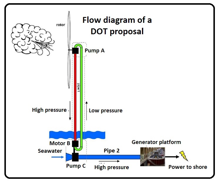
The Delft Offshore Turbines (DOTs) project aims to circumvent the need of the generator by using the rotor shaft torque to power a pump in the nacelle. This, along with the proposal to have a two-bladed rotor, will lead to a significant reduction in weight of the rotor-nacelle assembly.
One of the fundamental parts of the DOT is the hydraulic transmission. The PhD research project in this report focuses on the design of a seawater-based high pressure hydraulic energy transmission system, from the rotor shaft to the generator platform. This PhD project was set up as follows. First a plan for the overall DOT project was drafted (part I) to lay the foundation on the basis of which up to 8 PhD students can select research topics. The next step was to select one of these topic for my own research project.
Before any form of design could start a study was performed to look at the possibilities of using fluid power for wind energy transmission. This was the subject of the European Wind Energy Conference (EWEC) 2009 paper (part II). The purpose was to gain insight in how fluid power circuits operate. This meant mapping which type of systems exist, which is the most efficient and why and what the key performance indicators are. Gain insight in the applications and the potential of fluid power circuits, i.e. what has already been done with fluid power in similar applications, in general and hydraulic wind turbines in particular.
The next step was to perform a research based selection of the pump type and a first look at seawater as hydraulic fluid. This was the subject of the European Offshore Wind (EOW) Conference 2009 paper (part III). The goal was to select the best suitable pumping principles and investigate their commercial availability. Next to that insight was gained into which challenges arise from using seawater as hydraulic fluid.
Fluid Power Applications
High pressure fluid power has been applied for many years in many industries. The number of applications continues to grow. One of the earliest large scale projects were the Victorian age tap-water hydraulics. Pumping stations outside the center of cities like London, New York and Melbourne delivered water pressurized up to 60 bar through underground mains to power facilities like elevators, cranes and even theater curtains. Nowadays, fluid power is used in shredders, feeders, roll mills, cranes, bulldozers, jack-up systems, etcetera. These applications use electricity to efficiently acquire power in the form of high torque through high pressure fluid transmission. The DOT energy transmission concept is the exact opposite. High torque is converted into a high pressure flow.
Classification of pumps
Pumps can be divided in two general categories: kinetic (or hydrodynamic) and positive displacement pumps. In hydrodynamic pumps such as centrifugal pumps, the flow is continuous from inlet to outlet and results from kinetic impulse given to the fluid stream. The output is characterized by low pressure and high volume. Inefficiency and easy stalling as a result of back-pressure make these pumps unsuitable for control. In positive displacement pumps, fluid flows through an inlet into a chamber. As the pump shaft rotates, the (positive or definite) volume of fluid is sealed from the inlet and transported to the outlet where it is subsequently discharged. The essential difference between these two main categories is that kinetic pumps are for fluid transport systems and PD drive systems are for fluid power systems.
The power-to-weight ratio of pd pumps is much higher than that of the generators used in wind turbines. This is without taking into account all the extra components required for the use of an electricity generator.
The WE@Sea project 2004-012
Filed Under: News, Turbines