Nicholas Waters, bachmann electronic Corp
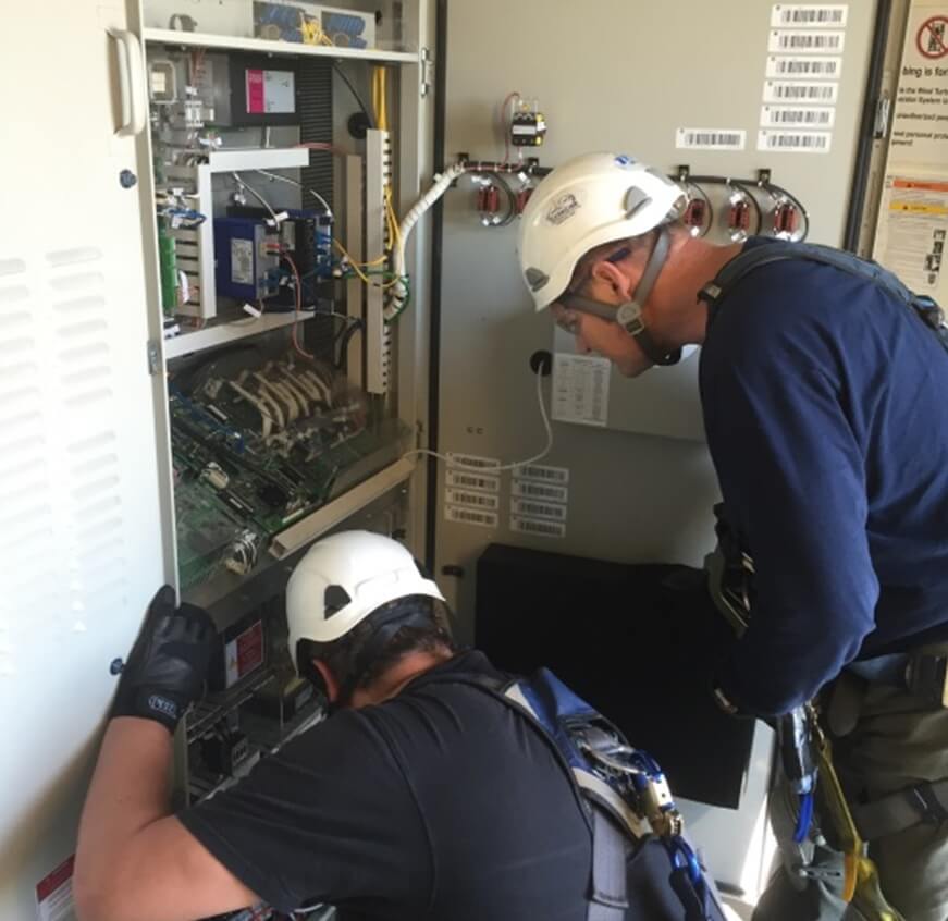
Bachmann’s Matthew Mays (back to viewer) and teammate install CMS into a wind turbine.
When I talk to a customer for the first time about condition-monitoring systems (CMS), I like to get an idea of their familiarity with the technology by asking how much they know about it. Most engineers respond with some reference to the Fast Fourier Transform (FFT) or the frequency spectrum. For those unfamiliar with FFT, this is a tool that converts raw vibration signals from the time domain to the frequency domain where most of the analysis or diagnostics takes place.
For a customer to mention the frequency spectrum – one of the more challenging hurdles to clear on the path to understanding vibrations for machine diagnostics – tells that the predictive-maintenance community has made huge progress towards educating wind professionals on CMS.
For those in the market for a CMS for their turbines, whether installed as a retrofit project or factory installed by the OEM, understanding a basic analysis isn’t enough to make an informed decision about which CMS option is right for their fleet. This is because condition monitoring starts with the sensors and ends with the analysis. The quality of vibration analysis has an asymptotic relationship with the quality of the sensor data because the analysis can only be as good as the data it relies on. To avoid putting the cart before the horse so to speak, the conversation should actually start with, “How much do you know about accelerometers?”
A fundamental truth that comes with all rotating machinery is that whether the machinery is deemed “healthy” or on its last leg, it vibrates. Interactions between components that make up the turbine drivetrain cause vibrations to propagate through the structure, contributing to the overall vibrational signature of the system. As vibrations travel through the structure, they are influenced by the shape and material of the components they pass through, as well as by their collision with incoming vibrations. The goal of each CMS system is then to separate each vibration source and analyze each source independently of what’s going on throughout the rest of the machine. Proper sensor selection comes into play when separating vibrational signatures that are close in frequency or boosting low-amplitude signals over the background noise of the system.
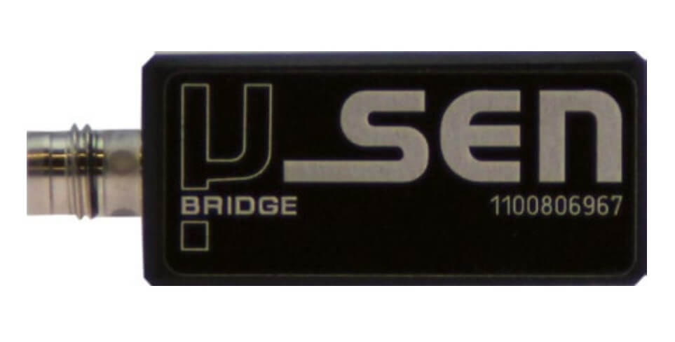
Bachmann developed the μ-bridge sensor to capture sound waves and flexural vi-brations in machines and plants (e.g. on components and solid bodies). It is a proprietary low-frequency sensor intended for early detection of faults on the main bearing.
There are two types of accelerometers that make up a CMS package: high-frequency accelerometers and low-frequency versions. Their sensitivity is also a consideration.
Sensitivity is a measurement of electrical output per mechanical excitation and is reported as mV/g (sometimes pC/g). For wind-turbine applications, a typical high-frequency accelerometer will have a sensitivity of 100 mV/g and is capable of measuring up to 80g.
High-frequency sensors monitor the high-speed section of a drivetrain (helical stage and generator) where defects produce clear and distinct peaks above the noise floor, making detection relatively easy. Defects that appear in the high-speed section produce a lot of energy and reduce the need for extremely sensitive sensors. To detect faults in the high-speed section, a sensor must measure higher amplitude signals without overloading the sensor.
Low-frequency accelerometers typically have a sensitivity of 500 mV/g (some vendors will list 250 mV/g and 350 mV/g as low-frequency accelerometers) and are capable of measuring up to 10g. The low-frequency accelerometer provides increased sensitivity for detecting defects in slow rotating components. Defects in the low-speed section of the drivetrain are difficult to detect because of the slow rotational speeds of components. This results in low-amplitude excitations caused by the defects. The 100mV/g accelerometer provides a high-level overview or big picture of what is going on whereas the 500 mV/g accelerometer provides a closer look at the low-frequency vibration data, giving increased visibility into a smaller portion of the spectrum. The 500-mV/g accelerometer sacrifices some high-end frequency data, but it increases the low-frequency detection capabilities. To achieve the full potential of a CMS solution, it is pertinent that a CMS option comes with both high and low-frequency accelerometers.
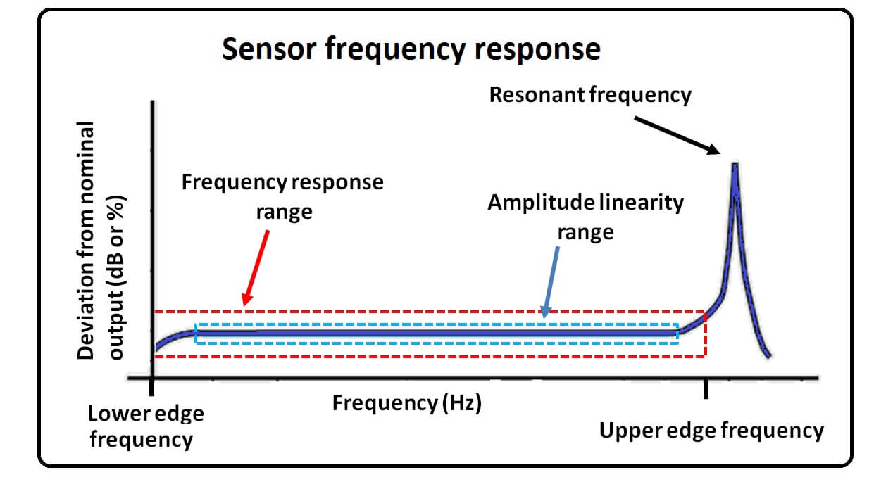
A sensor’s frequency response.
When benchmarking one CMS system against another, it is important to understand that not all high or low-frequency accelerometers are the same. Frequency response provides a frequency range that the sensor operates over, and output tolerances across the frequency range that is either in decibel (dB) or percent. For frequency response, look for sensors with the widest frequency range, the lowest lower-edge frequency, and the tightest tolerances over the specified frequencies (Sensor frequency response graphs some sensor ranges).
At Bachmann, our standard high-frequency accelerometers (BAM100) have a sensitivity of 100 mV/g, are capable of measuring up to 80 g, have a frequency response of 0.5 Hz – 14 kHz (±3 dB), and have an amplitude nonlinearity of 1%. Our standard low-frequency accelerometers (BAM500) have a sensitivity of 500 mV/g, are capable of measuring up to 10 g, have a frequency response of 0.2 Hz – 14 kHz (±3 dB), and have an amplitude nonlinearity of 1%.
The frequency response can be reported in multiple frequency intervals with different tolerances reported for each interval. The amplitude linearity specifies the sensor’s deviation from the nominal output over the linear region of the sensor’s output. It is especially important for a low-frequency accelerometer to have a low value for the lower-edge frequency and a tight tolerance to increase the ability to detect faults within the slow-speed section of the drivetrain.
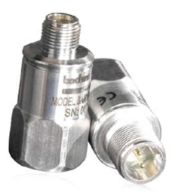
The BAM100 (high frequency) and BAM500 (low frequency) acceleration sensors come with robust insulated housing and hermetic sealing for demanding ambient conditions.
Another point worth mentioning is the use of triaxial instead of single-axis accelerometers in sensors. Although obtaining vibrations in all three axes is taught as one of the fundamentals of vibration-based condition monitoring, in practice this is not typically implemented because of cost and sensitivity. In a wind-turbine specifically, frequency response marks the difference between a narrowly caught pending failure and a fault missed altogether. Standard triaxial sensors have a lower-edge frequency of 2 Hz, meaning they don’t typically perform as well in a low-frequency range compared to standard single-axis accelerometers. In addition, triaxial accelerometers only report about 80% of the signal strength in the two axes normal to the mounting axis. A few CMS vendors provide CMS units capable of achieving a 99%-plus detection rate throughout the drivetrain without the use of triaxial accelerometers, so the added cost of a triaxial is not worth the purchase.
In summary, when selecting the right CMS for a fleet, make sure the system consists of a combination of:
- Low frequency (for low-speed components).
- High-frequency accelerometers (for high-speed components).
- Sensors that have a broad frequency response range with a small value for the lower-edge frequency.
- Low deviations in their reported amplitude linearity.
Unless cost is not an issue, go with a system that uses single-axis accelerometers. Lastly, be prepared to answer the question: How much do you know about accelerometers?

Author Nicholas Waters
Nicholas Waters is the Key Account Manager for Bachmann electronic North America. He joins the wind industry with a background in research and development focused on structural health monitoring (SHM) and condition based maintenance (CBM). Nicholas is a Mobius certified Category II Vibration Analyst with a M.S. in Ocean Engineering from FAU and a B.S. in Applied Mathematics from UC Davis.
Filed Under: News