By Simon Searle, Applications Engineer
Megger

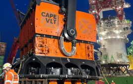
A wind tech, suited up in fall-protection gear, safely rappels down to a turbine blade to test the asset’s lightning-protection system during an onsite O&M visit
One of the most significant hazards wind turbines face is damage from lightning strikes. Damage claims caused by strikes are one of the top payouts from insurance companies. A recent German study found that up to 80% of insurance claims relating to turbine downtime were from lightning-related damage. In fact, lightning accounted for nearly 85% of one commercial wind farm’s downtime in the United States — costing the owner an extra $250,000 in the project’s first year of operation.
Another large wind farm in the North Sea, near the German island of Helgoland, suffered such large losses because of lightning strikes that its operation was no longer cost-effective.
Lightning faults are unlike typical electrical faults and cause a greater loss in wind-turbine availability and production. The number of failures due to lightning strikes is known to increase with tower height, and a number of studies indicate that rotating wind turbines may be more susceptible to lightning strikes than stationary structures. Given that turbine heights are expected to increase and the industry is growing, the number of turbine failures is likely to rise as well.
Lightning damage to turbines is often attributed to inadequate strike protection, incorrect or insufficient bonding and earthing (grounding), and insufficient transient protection. In addition to a direct strike to a blade, high-energy over-current and over-voltage transients induced by direct and indirect lightning strikes can cause significant damage when these massive structures are left unprotected.
Proper protection & testing
One way to reduce the likelihood of strike damage is to build lightning protection directly into wind turbines.

When an unprotected wind-turbine blade is struck by lightning, its temperature will rise (as high as 54,000 F) and severely damage the surface of the blade. It may also melt or crack the blade’s leading edges. Here, the image shows the entry point of a strike.
This form of protection follows a low-resistance path to ground and travels from a turbine blade’s tip to the base of its tower. In the event of a lightning strike, current flows through the protection system and directly to ground, avoiding sensitive equipment in the machine.
It is critical the protection system stays online at all times, and works immediately when required. To do so, the resistance of the path to ground should be measured at regular intervals, ensuring it meets the limits specified by the turbine’s manufacturer (typically, the path is limited to 15 to 30 mΩ, but this depends on a turbine’s size).
For such a test, it is best to use a low-resistance ohmmeter. The most important device to test is the conductor inside the blade. This measurement is taken between the blade’s tip and root. A current of one ampere or more is recommended for the test.
However simply checking the continuity, which verifies the flow of an electrical current, is insufficient. This is because the conductor may undergo a significant amount of strain and fracture as the blade flexes in the wind. If the fractured conductor is touching at the breakpoint during a continuity test, it may still pass the test.
The problem with blades
The length of wind-turbine blades is a challenge when testing built-in lightning protection because low-resistance continuity test leads are typically extremely short. Adequate testing requires extra-long leads that are often up to 100m. In addition, these long leads must maintain a low enough resistance to ensure that accurate measurement is possible.
To achieve this, an understanding of the test instrument design is important. For example, some instruments have a compensation factor, which allows for power loss in standard test leads. When using long test leads, however, the compensation for power loss is insufficient and the test range of the instrument reduced.

The wind-turbine lightning protection test lead set from Megger is available in a 328 ft. (100m) length, and is suitable for use on site or in the manufacturing plant. The lead set is 10A rated and consists of two test leads. The first cable is 16 ft. (5m) and the second is 328 ft. (100m). The lead set offers reversible terminations. One termination is a duplex handspike, and the other is a heavy-duty Kelvin clip.
How it works: When the resistance of the test leads is increased, the total value of “R” in the equation below will also increase.
P=I2R
R = (resistance of load) + (resistance of test leads)
P = output power of the test instrument
I = output current of the test instrument
Since the maximum power output (P) of the test equipment is unchangeable, the rise in test lead resistance will cause the maximum current (I) to diminish.
However, this principle may be used to an advantage. If the load is inductive, it may help if more power is supplied to charge the load. By reducing the length of the test leads, “R” will diminish.
In this situation, it is “P” that will increase slightly, as there is a little more power in the instrument than specified on the data sheet. This is intended to compensate for the losses of a few meters of test leads, but if the test leads are kept extremely short, then the extra power is available for the load instead.
Filed Under: Lightning protection, News, O&M


Hi,
I am a vocational tutor in a prison teaching basic electrical skills. This morning I had a discussion with my class about lightning protection and was asked whether individual turbines were susceptible to strikes. I did some research at lunchtime and came across this article which was very helpful. I would be interested to know if you have any other materials that I could use in my class. Thanks, Stewart