Daniel Provost, Owner, New World Technologies
The objective for calibrating a torque tool is to ensure that it applies the torque the tool indicates it is applying. Transducers – the sensors used to measure torque applied by the tools – come in many different sizes and torque ranges. Those most commonly available for the wind industry have 0.5 to 1.5-in. square drives and torque ranges from 100 to 10,000 ft-lbs.

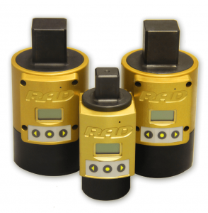
The RAD Transducer Series comes in torque ranges up to 7,000 ft-lbs along with a calibration certificate from an ISO 17025 accredited lab.
For instance, a conventional click-type torque wrench typically uses a handle with engraved markings that are rotated to align with the incremental values on the shaft of the wrench. Compressing a mechanical spring and cam produces an audible click at the indicated specific torque value
Hydraulic torque wrenches require a calibration process, which usually involves two tiers. The first verifies the actual torque output of the hydraulic tool. This is done by gradually increasing the hydraulic pressure to the tool while it is on the calibration stand and connected to a static digital read out transducer. The calibration technician will verify the torque output from the transducer and compare it to a precision hydraulic-pressure test gage.
In the second tier, the hydraulic pressure gage on the pump that accompanies the wrench is removed and tested against a precision-calibrated test gage.
Torque up to 1,500 ft-lb is classified to BS 7882:2008 as Class 1 or better for the primary range (±0.5% of reading from 20 to 100% of full scale). From 1,400 to 7,000 ft-lb is classified to BS 7882:2008 as Class 0.5 or better for the primary range (±0.25 % of reading from 20 to 100% of full scale) benches. When the pump gage is not reading properly, it should be changed out.

The RAD 1500 Transducer Systems allows calibrating torque wrenches and those with ratings up to 1,500 ft.lbs.
Electronic torque-wrench calibration differs from the static testing of hydraulic wrenches. Electronic gear-reduction tools must be tested and calibrated dynamically. Electronic tools deliver constant rotational drive right up to final torque, unlike hydraulic versions which rotate at 25° per activated stroke.
The calibration equipment needed includes a calibration stand to hold the transducer and dynamic rundown fixture. The stand must be able to carry the high reactionary forces produced by the tool.
Qualified technicians calibrate electronic tools by comparing the digital readout on the tool to the actual readout from the transducer. When they are not within tolerances a technician can adjust the calibration angle in the tool which is based on a percentage of current drawn for that torque value.
The period between recalibrations differs from manufacturer to manufacturer. In most cases, the period would be one year after initial factory calibration. Electronic torque tools may have a cycle counter built into the software which can be set to alert the operator that a calibration or re-torque is due. In many cases, re-torquing can be done in the field making it unnecessary to dispatch the tool to a service center.

Aside from static transducers, the company also manufactures the RAD Smart Socket which allows for field calibration on a live application – on the job.
Calibration transducers should also be re-calibrated on a regular basis. This process can be done by accreted laboratories (usually ISO 17025) that would be equipped with certified test beam and weights. RAD Transducers are classified to BS 7882: 2008 or better for the primary range (±0.5% of reading from 20 to 100% of full scale)
New World Technologies (manufacturer of the RAD Torque Systems) has been building and calibrating gear reduction torque wrenches for over 20 years. The company considers calibration of all its tools (pneumatic, battery, and electronic) critical to their performance and accuracy.
Over the years the company has used transducer from various manufacturers in an attempt to find a best system for its gear reduction drive tools. In 2013 the company began manufacturing transducers in house for the tools it produces.
Filed Under: News, O&M


