Data indicates a high occurrence of elevated combustible gasses in cabinet style, wind-farm transformers. Studies presented here are a first step to understanding and helping solve the problem.
Luke J. Parthemore /Technical Data Analyst Supervisor/Robert (Bob) T. Rasor, PE/Director of Engineering/SD Myers Inc., www.sdmyers.com

Before accessing cabinet-style transformers, technicians must wear personal-protection equipment to protect against arc flash and other hazards. Devices, such as SD Myers’ SampleSafe, (inset) allow accessing the transformer in a safe manner.
Over the past few years, analyzing wind-farm transformers for dissolved gasses has presented a myriad of challenges because the analyses found significantly elevated gas levels. Wind farms are unique in that they deal with constant changes in the energy supply. Wind power involves high-efficiency generators which typically require converting and conditioning the power prior to transmission. One of the more conventional components in these systems is the cabinet-style transformer that steps up the generator voltage for transmission. The focus of this discussion is placed on these cabinet-style collection transformers and the conditions evidenced by dissolved-gas analysis.
IEEE guidelines
IEEE C57.104 provides guidance for gas concentration limits and a retesting frequency based on limits for each key gas, limits for total combustible gases, and the rates at which the combustible gases are rising. Based on the total concentration of combustible gases the transformer is assigned a “condition” rating from 1 to 4. Recommendations for retesting can then be determined by the condition level and the rate at which the transformer is generating combustible gases. The IEEE recommends these minimum retest frequencies: Condition 1, annually; Condition 2, quarterly; Condition 3, monthly; and Condition 4, weekly. Greater frequencies are recommended when the generation rate of combustible gases hits 10 ppm or more per day.
These guidelines have been used for the comparisons included in this article. It should also be noted that the study of gases in wind-farm transformers was initiated by SD Myers Inc. diagnostic group based upon concerns that applying the guidance strictly to the generation of hydrogen was resulting in what appeared to be excessive retesting on these transformers. Although the other gases raise concerns, hydrogen will be a main theme of this review. While hydrogen is mainly an accompanying gas in many fault conditions, it is primary in the fault detected in many of these wind-farm transformers.
The data contained in this paper were derived from the laboratory histories of more than 6,000 individual mineral oil-filled cabinet-style transformers installed in wind turbine collection systems. These samples were taken from transformers in more than 60 locations and involved transformers produced by more than 20 different manufacturers between 1984 and 2009. As an important comparison, it seemed prudent to have a dataset of distribution (non-wind farm) cabinet-style transformers of a similar size (6,000 count).
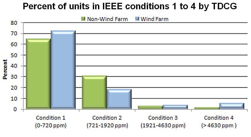
The chart below illustrates the percentage of cabinet-style transformers that fall into each IEEE Condition category for wind farm and non-wind farm cabinet-style transformers based on Total Dissolved Combustible Gases (TDCG). Some of the data reflected in the chart may be biased due to age, but nonetheless, it indicates that cabinet-style transformers, in general, have a rather high rate of gassing.
These results would also indicate that while most non-wind-farm transformers level off at Condition 2, a much larger number of units continue on to Condition 3 and 4. Noting that a large percentage of the wind-farm transformers are relatively new, one might expect the percentage of Condition 3 and 4 units to climb over the next few years. Our current data show that more than 3.5% of these units have a TDCG of greater than 9,620 ppm. This is twice the starting concentration for Condition 4. In a great many cases, these extremely high concentrations consist primarily of hydrogen.
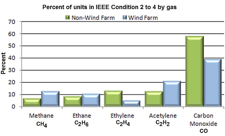
Standard guidance for acetylene states that any concentration in excess of 1 ppm is considered to exceed Condition 1. The next chart illustrates that about 21% of wind-farm transformers exceed the Condition 1 limit while cabinet transformers in non-wind applications show about half that amount. Additionally, nearly 18% of the wind-farm units fall under Condition 2 (2 to 9 ppm), which may suggest that the switching practice (placing transformers on and offline) influences the acetylene results.
The final chart illustrates a comparison of non-wind and wind-farm cabinet units that merit Condition 2 and higher for hydrogen. Obviously, this is an area where wind-farm transformers really stand out. In fact, greater than 23% of wind-farm transformers merit Conditions 2 to 4 for hydrogen. In comparison, only 5.3% of units in non-wind applications merit these same classifications.
The chart to the left also illustrates that nearly 29% of all wind-farm transformers contain greater than 720 ppm in TDCG meriting a Condition 2 or higher according to IEEE guidelines. The data in the last chart shows that nearly 40% of that population of wind-farm transformers reaches the condition rating due to hydrogen alone.
Two primary conditions or faults generate hydrogen: Electrolysis occurs in the presence of excessive moisture. If moisture in the form of free water passes through or is present in areas of electrical stress or reacts with certain metals, the water breaks into its basic components of hydrogen (H2) and oxygen (O2). However, in a separate evaluation, moisture would have to be present in sufficient amounts to cause the condition.
Partial discharge, a more likely scenario, relates to another condition. In simple terms, partial discharge is a voltage potential attempting to create a path through any part of the insulation to ground or other voltage potentials. These high-stress conditions are often the result of tight electrical clearances, or voids in the insulation, or both. The source of partial discharge is often hard to identify because, in many cases, the fault occurs in the oil and there is no evidence left behind that would be found by visual inspection.
Theories on causes of gassing
Clearly there is much work to be done before all the issues associated with wind-farm transformers can be understood. The industry is in need of standards that might guide wind-farm owners to more trouble-free and reliable systems. The cooperation and input of all the interested parties throughout this industry is needed to support the effort. Involvement in task force studies in conjunction with IEC and IEEE are an important step to identifying the cause of and solving this problem.
A few theories on causes include:
- Many believe harmonics are to blame for many of these gassing issues, and likely with good reason.
- A transformer improperly sized and incapable of handling unique conditions of wind power can result in severe heating and dielectric stresses that exceed the capabilities of the insulation system. Either of these would result gas generation.
- Some believe extreme cycling between heavy and light loads may cause the formation of gas bubbles in the oil. So, this leads to a suspicion that the typical cabinet-style transformer may not be ideally suited for wind farms. In typical non-wind applications, these transformers provide cost-effective solutions and reasonable reliability, but are they always adequate for wind-farm work?
- Some information shows many wind-farm transformers are manufactured with economical rectangular, layer-wound coils. Although layer windings have positive aspects, could it be argued that by construction, these coils are susceptible to voids in the insulation?
- Strings of these cabinet units, along with the yet-to-be-quantified notion that the first and last units are affected, may be another cause. Switching operations can also create stresses on these transformers and particularly on the end units where a number of units are daisy-chained in a parallel circuit. These are just a few examples from an extensive list.
What can we conclude?
The alarming level of gases in wind-farm transformers is supported by the data shown in this article. Hydrogen in particular is to be managed with concern. However, to date, based on our initial industry interactions, there has been limited feedback on what is thought to be a combination of the causes previously mentioned. Addressing the guidance and retest intervals are of concern for numerous owners, to say the least.
More importantly, a search for solutions is needed to increase system reliability and reduce or eliminate safety risks. The industry must respond with input from manufacturers, users, and those responsible for monitoring and maintenance. WPE
Filed Under: News, O&M, Transformers



Many Wind Farm Operators (Desert Sky, Whites Creek, Colorado Green) have used on line automated vacuum degasifying oil processing systems (AUTOS) to process the oil to reduce combustible gas levels and allow the transformer to remain in operation.
Very interesting data. It seemed that your text referenced some graphs that were not included in the article, for example the final chart comparing wind and non-wind cabinets that merit condition 2 for hydrogen. Why is hydrogen not included in the first chart?
It would be worth while to conduct an in-depth study on intermittent corona occurring within the units under specific conditions. Irregular loads could intermittently over stress the insulation resulting in partial discharges of short duration.
Sometimes gassing itself is not a fault, just stray gas phenomena.
Second option is the demand for non-mineral oils, is not yet fully understood, especially in combination with usual solid insulation.
Using a IEEE guide is not a good reference for this type of units, it will tell us that there is a problem where there is not. Certainly this type of tools could help us to diagnose our units as it works for power transformer. On the other hand replace the mineral oil with a higher viscosity oil would give you cooling problems in the coils, so it sound risky that alternative
This is very similar to what we have noted going on in 1 mva transformers at a solar farm. All 5 of our transformers are Condition 3 for CO and CO2, and Code 2 for H2 (all at 100 ppm or slightly more). Our tester believes that our cellulose is being degraded. I have researched this and found that replacing the mineral oil with FR3 has been used to help slow the rate of cellulose degradation in other applications. Any thoughts?