Several techniques are available for finding a bearing’s failure mechanism in a wind-turbine gearbox. Once established, a root-cause analysis can determine the origins of the failure mechanism.
Michael Hornemann, Reliability Engineer
Dr. Ashley Crowther, VP of Engineering, U.S. Technical Center, Romax Technology Inc, www.romaxtechnology.com
Drive-train failures in wind turbines are often expensive to remediate due to crane fees, replacement component costs, man power costs, and lost production. A sound understanding of failure modes and corrective actions is required for wind turbine owners and operators to better manage the drive train lifecycle.
This article focuses on the techniques to establish the bearing failure mechanism in a wind turbine gearbox and the process of root cause analysis (RCA) to determine the origins.
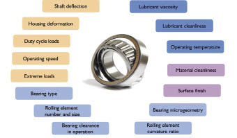
Consider these factors when selecting bearings. Incorrect assumptions on any of them can lead to a shorter bearing life.
Recent standard revisions
The recently revised standard for wind turbine gearbox designs, ISO 61400-4, requires sizing gearbox bearings per ISO 281 and ISO 76, which include calculations for two failure modes:
• Sub-surface initiated, rolling contact fatigue and
• Yielding under maximum stress.
 The standard also mandates items such as bearing steel quality (to meet ISO 683-17), values for parameters involved in the sizing calculations, and how design loads should be applied. The standard also provides good advice to the application from a design perspective, because the failures often seen in the field are not related to the bearing meeting the design calculation for these two failure modes. For instance, we see failures related to end loading, bearings races spinning in their fit, surface originated fatigue, and retainers coming loose. Bearing selection considerations illustrates some of the factors involved in bearing performance. Each or several can influence a premature bearing failure, that is, where the life is much less than that found by the design-life calculation.
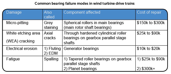
ISO 15243 is a useful standard to classify the damage. The accompanying table provides a few examples of bearing failures in the wind industry and their associated costs. Note that damage classification is not a root cause of failure. One or more initiating factors are often behind the observed damage.
The first step for a proper bearing root-cause analysis (RCA) is to remove the bearing from the gearbox, separate the rings and rollers, and determine the failure origins. Prior to removing the bearing from the housing, it must be photographed to document the as-found condition. It is helpful to write on the components with a paint pen to indicate part orientation prior to removal from housing. Look for evidence that the outer ring has spun in the housing or that the inner ring has spun on the shaft journal, abrasive wear and the nature of fretting corrosion often provide valuable clues.
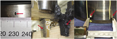
Take a closer look at three common wind turbine drive train bearing failures. (Left) This initial macropit and debris damage is on a tapered roller bearing. (Middle) A main-bearing cage shows imbedded debris (arrow) and blackened grease. And, a cylindrical roller bearing shows assembly damage at the roller spacing.
The bearing rings must be separated carefully without damaging any evidence. Bearings generally are held together by rivets in the bearing cage, snap-rings, or end covers. Bearing disassembly is not without hazards and a proper risk assessment should be conducted and reviewed by the site safety manager prior to commencing work. Some of the hazards that must be mitigated during bearing disassembly include:
• Bearings are often heavy with no built-in handling points. Create a lifting plan to avoid dropped parts and musculoskeletal injuries.
• Eye protection, gloves, long sleeve shirts, and a machinist’s apron are all required to protect against metal chips when using a drill press to remove cage rivets.
• Proper ventilation and gloves are required when using solvents to clean bearings.
Once the bearing-failure mode has been identified the root-cause analysis begins to determine the failure origin. Root cause analysis must follow an orderly process to achieve conclusive results. A typical RCA for a wind turbine bearing failure will incorporate the following 12 steps:

The fishbone diagram is for a typical bearing failure, root cause analysis.
1) Project definition and project management
2) Identify potential causes
3) Review existing documentation
4) Machine data review
5) Up tower inspection and measurements
6) Lubrication analysis
7) Factory teardown and inspection
8) Metallurgical investigation
9) Simulation
10) Future failure risk assessment using Weibull distribution analysis
11) Corrective action recommendations
12) Document the root cause findings
Documentation requirements, established in Step 1, must be followed by all parties involved in the RCA.
This article from here focuses on two key steps in the RCA process: Identification of potential failure modes and Metallurgical investigation. These steps should be performed by engineers who are experts in bearing failure investigation.
Failure mode identification
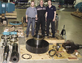
A Romax team takes a break during a gearbox disassembly and investigation.
To identify all potential causes for failure, it is essential to assemble all persons with knowledge of the wind turbines operation as well as relevant experts for a brainstorming session. The goal of the meeting is to leave no stone unturned and list all potential causes so they can be formally addressed to construct an Ishikawa or fishbone diagram that organizes the potential causes into groups. After creating the diagram, the group ranks each potential cause by its perceived influence on the failure. To help guide the team to the root cause, items ranked with a Moderate, High, or Further Analysis influence factor should receive additional investigation. The group then defines the documentation or operational data that must be reviewed, or testing that must be performed prior to eliminating the item as a potential root cause.
Metallurgy
To verify the items shown in the “Materials” bone of the accompanying diagram, it is often necessary to send the failed bearings to a qualified metallurgical laboratory for testing and review by a metallurgist. The bearing may be sectioned at the lab, for example, in axial and circumferential directions with samples prepared as shown in accompanying photos (Page 68).
Many tests can be performed so an initial round of testing often includes:
1) Chemical composition
2) Surface and core hardness
3) Case hardness depth for carburized components
4) Grain size
5) Steel cleanliness
6) Microstructure
7) Nital etch
8) Microscopic and scanning electron microscope (SEM) analysis of cracked regions
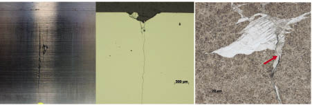
The images come from a metallurgical examination of an axial crack in a bearing inner ring. (Left) The axial crack as it appears on the surface. (Middle) A metallurgical microscope image is of the sectioned bearing. And, an SEM image shows an irregular white etching area formation which has produced a micro-crack (arrow) that lead to the formation of the axial crack.
Much can be learned about the failure mode from these tests, such as evidence of grinding burn under the Nital etch, evidence of sub-surface cracks originating from inclusions, an inadequate material hardness, or a unsatisfactory steel microstructure.
When any of the above tests prove that the material was insufficient, then a study must be conducted of the manufacturing quality documentation to identify a total affected population. If the metallurgical testing does not reveal a root cause, then the investigation should focus further on the gearbox design, assembly, and operation.
Romax routinely performs RCA on failed wind-turbine bearings and finds that critical tasks in the investigation generally include a factory teardown, metallurgical study, and gearbox or bearing simulation. A root cause can generally be identified with a detailed approach to these tasks buttressed by the significant application expertise. This lets the OEM or owner transition quickly to assessment of corrective actions along with a risk and cost reduction. WPE
Filed Under: Bearings, Featured, O&M


I am interested in the technical explanation given in your failure analysis, having engaged in studies of similar kind; quite often white etched area is considered as region of concern; as a person engaged in physical metallurgy I wonder what is this white area quite often spoken about; in some places, it is referred as martensite; but the etchant should etch it; did you metallurgists study in detail.
Thanks in advance.
Param